47
ED900 02-202008125330
dormakaba ED900 Installation Instructions – Double egress door Chapter 14
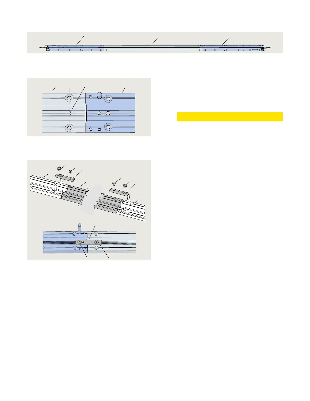
Fig. 14.4.4 Mounting plate assembly
5
5
6
5 Mounting plate,
operator .. Drill two holes in pair mounting plate for M
fastener.
. Drill hole in each end of pair mounting plate for M x
mm PFHS (Fig. ..).
.. Assemble mounting plates.
. Place the three mounting plates on a flat surface
(Fig. ..).
CAUTION
Verify mounting plate assembly dimensions with
installation template (Chapter ).
. Secure the operator mounting plates to the pair
mounting plate () using:
• () mounting plate connectors ()
• () M x mm SHS with washer (8)
• () M x mm PFHS ()
Do not tighten screws.
.. Check cover fit over ED operators.
. Place the ED operators onto their mounting plates.
. Place end caps () at end of each operator.
. Place cover over end caps and ED operator.
. Adjust mounting plates as necessary for cover fit
over end caps.
. Remove end caps and operators.
. Tighten mounting plate connector fasteners.
.. Mounting plate installation.
. Reference Chapter .
6 Mounting plate,
pair
Fig. 14.4.5 Pair mounting plate hole for M6 fastener
2.5 mm tap drill
6
5
5 Mounting plate,
operator
6 Mounting plate,
pair
Fig. 14.4.6 Mounting plate connectors and fasteners
4
4
8
8
9
9
6
5
5
4
8 9
4 Mounting plate
connectors
6 Front cover
extension
08121870
7 dormakaba logo
plate
08125241
8 M6 x 10 mm SHS
with washer
9 M6 x 10 mm
PFHS



 To Next Page