64
ED900 02-202008125330
dormakaba ED900 Installation Instructions – Double egress door Chapter 17
. Fasten arm to ED operator
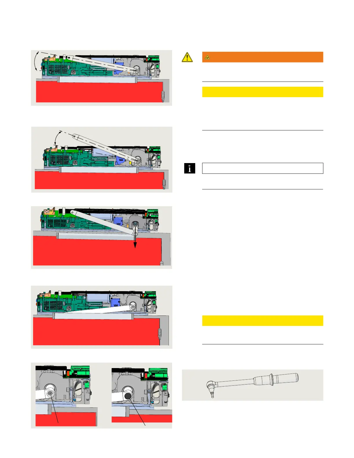
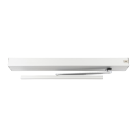
Fig. 17.9.1 Mount drive arm to operator at 12 degrees
Fig. 17.9.6 Torque wrench, 5 mm hex key
.. Mount drive arm to operator.
WARNING
Use caution when working in proximity of door
and pull arm!.
CAUTION
ED operator axle zero position.
In order to mount the drive arm in the correct
position, the spindle must be brought to the
zero position.
. Set ED operator spring preload to approximately ten
clockwise rotations.
• Axle rotates to the zero position.
TIPS AND RECOMMENDATIONS
Reference Chapter 19, Operator spring tension.
. Turn the spring preload back to zero rotations
(fully CCW).
. Push the drive arm onto the spindle at an angle of
approximately to the ED operator (Fig. ..).
. Rotate the drive arm/spindle approximately in
the door's opening direction (Fig. ..).
. Remove the drive arm from the spindle (Fig. ..).
. Position the drive arm one tooth in the door's closing
direction (Fig. ..).
. Push the drive arm / axle extension onto the spindle
(Fig. ..).
. Thread the M x ___ mm SHCS (length determined
by axle extension) into the spindle and tighten SHCS
(Fig. ..).
CAUTION
Use torque wrench with hex key socket to
tighten M screw to ft-lb [ Nm].
. Install cap over M SHCS (Fig. ..).
Fig. 17.9.2 Rotate drive arm 10 degrees in door opening
direction
Fig. 17.9.3 Remove drive arm
Fig. 17.9.4 Install drive arm and axle extension
Fig. 17.9.5 InstallM8 x __ mm SHCS into spindle
2
1 M8 x __ SHCS 2 Cap
1
12˚
10˚



 To Next Page