96
ED900 02-202008125330
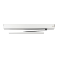
dormakaba ED900 Installation Instructions – Double egress door Chapter 32
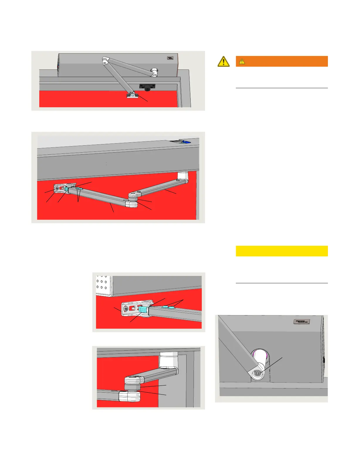
. Push arm maintenance
1 Drive arm
2 Adjustment arm
3 Adjustment arm
tube
.. Push arm maintenance.
WARNING
Set program switch to CLOSE
before performing maintenance!
. Adjustment arm.
• Check for wear or damage.
• Check tightness of M x flanged
button head screws (Fig. ..).
. Shoe and adjustment arm assembly:
• Check for wear or damage at shoe
bearing (Fig. ..).
. Adjustment arm socket and ball head
(Fig. ..).
• Check for wear or damage.
.. Shoe door mounting screws .
. Remove screw cover caps (Fig. ..).
. Check for tightness of mounting screws
(Fig. ..).
. Replace screw cover caps.
.. Drive arm to ED spindle.
. Remove spindle cap.
. Check tightness of M SHCS.
CAUTION
Using torque wrench with mm
hex key socket, torque M SHCS to
ft-lb [ Nm].
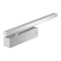
Fig. 32.6.1 Push arm assembly
Fig. 32.6.4 Arm socket and ball head
4 M6 x 10 button
head screws
5 Drive arm socket
7
2
9
4
Fig. 32.6.3 Shoe bearing
2 Adjustment arm
3 Adjustment arm
tube
4 M6 x 10 mm flanged
button head screw
7 Shoe
9 Articulated
bearing
11 M8 SHCS
6 Adjustment arm
ball head
7 Shoe
8 Shoe mounting
screws (2)
5
6
5 Socket
6 Ball head
Fig. 32.6.5 Spindle M8 SHCS
1
6
5
8
8
7
3
2
4
Fig. 32.6.2 Push arm assembly hardware
11
10 Screw cover caps



 To Next Page