DESCRIPTION AND INSTALLATION
25364 Issue 8 March 2018 2-27
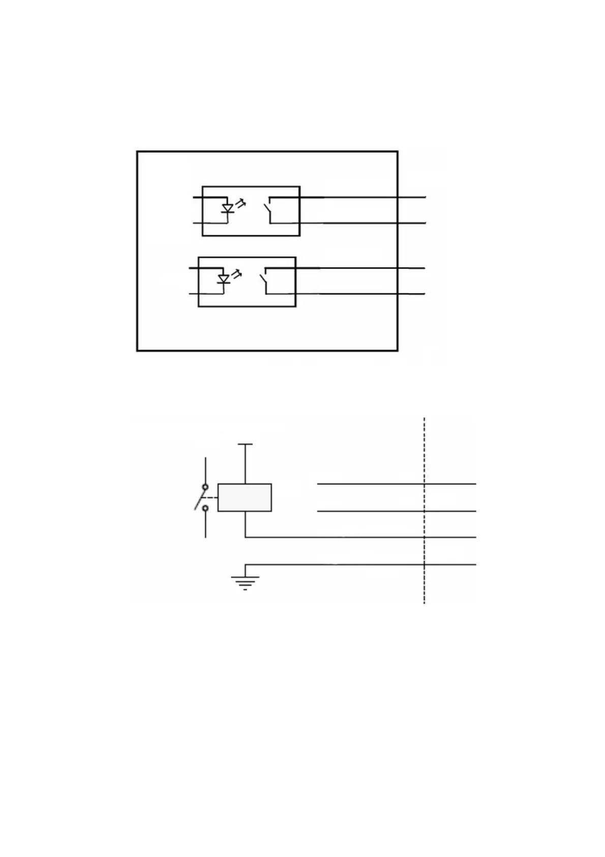
Output Connections - Communicator II
Outputs 1 and 2 are volt-free contacts with a maximum loading of 30V
100mA. See the pin allocation table on page 2-21.
Pin 12 (Light Green)
Pin 4 (Orange)
Pin 11 (Pink)
Pin 3 (Red)
Printer
Output 1
Output 2
I/O Connector
15-pin D-Type
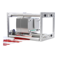
If the I/O box is changed from volt-free to NPN outputs, see Communicator
II Pin Allocations page 2-21. The output should be connected as per the
diagram below:
Light Green
Orange
Pink
Red
External Relay
3
11
4
12
Relay
24V
Error
Ready
The internal switch for the output signal can handle a maximum of +30V
and 100mA. The internal switches pull down the signal level to ground.
Therefore it is very important to mount pull-up resistor(s) and/or a relay(s).
CAUTION: Never connect external voltage directly to the error
and r
eady output without a pull-up resistor.
Recommended pull-up resistor at +5V: 470 ohm
Re
commended pull-up resistor at +24V: 2.2 kilohms