Version 2.02 15.05.2007
Function of VS 3000
33
eckelmann.de
E 2007 - ECKELMANN AG | BERLINER STRASSE 161 | 65205 WIESBADEN | TELEFON +49(0)611 71 03-0 | FAX +49(0)611 71 03-133
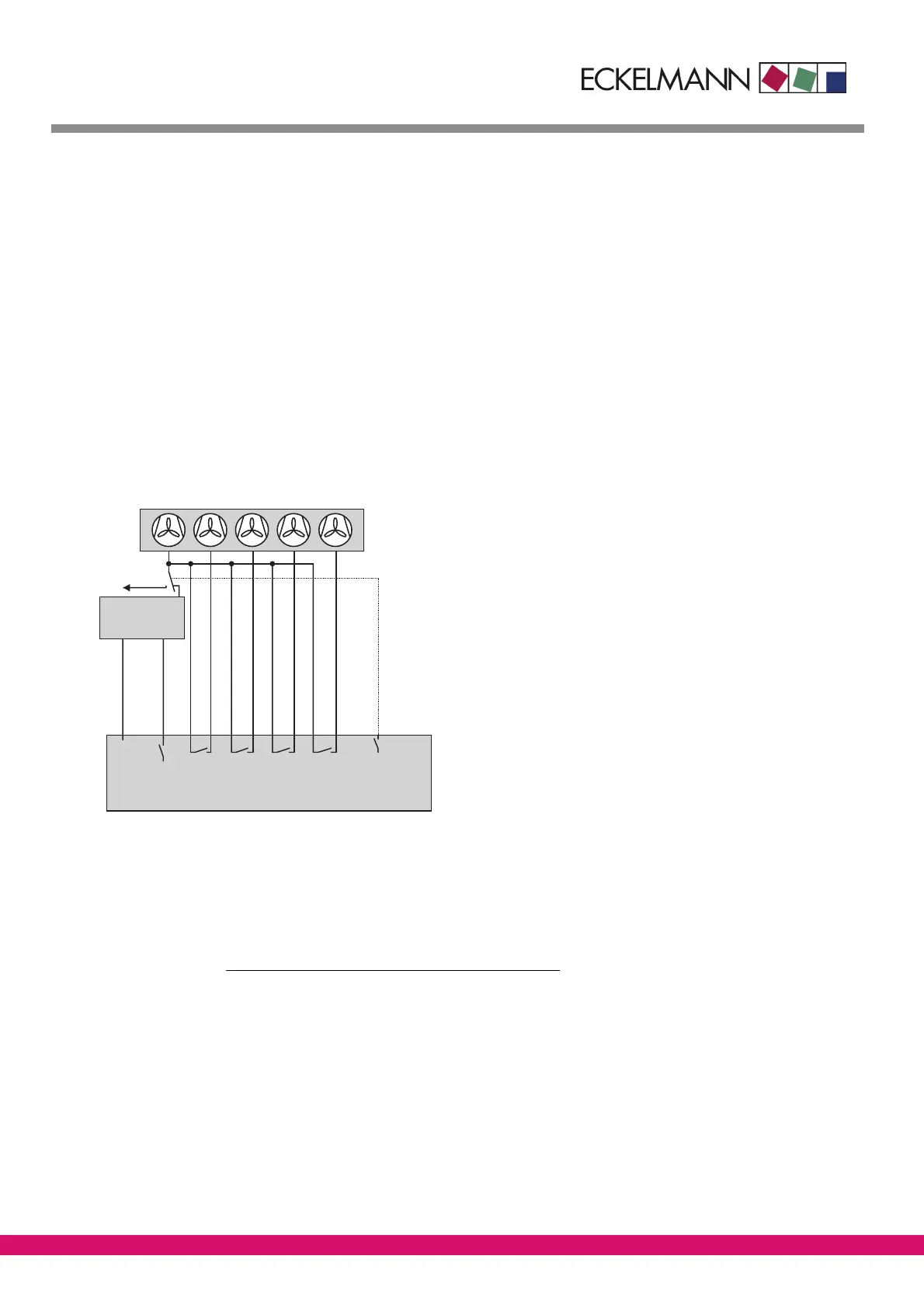
3.27.8.1 Control algorithm with parallel combined controller
High pressure detected by an A/D converter is compared with the setpoint. The following relationship
applies:Controlerror = Actualvalue (t
c_Act
) − setpoint (t
c_Setp
)
Using a PI control algorithm, a speed setpoint is calculated as a function of the control error and supplied to the
speed adjuster via an analog output (0 - 10 V), see Section 1.27.8. The speed adjuster c ontrols the speed of all
parallel-connected fans, which can be loaded or unloaded separately. Depending on the VS 3000 expansion
stage the number of fan stages that can be controlled is as follows:
- VS 3000 basic configuration: 3 fan stages
- One SIOX extension module added: 7 fan stages
- Two SIOX extension modules added: 11 fan stages
With HP combined control the available number of fans as a function of expansion stage is accordingly one less
than with step control. The reason for this is that the fan output following the last definable fan output
(No.Cond.Stages XX, Menu 3-1) is used for toggling to fixed-speed operation.
L1
L2 L3
L4
Ln
Ln+1
0-10V
VS 3000
Speed
adjuster
ZNR. 51203 74 830 E0
Power supply
Enabling
Operation
by power supply
Control signal
With a positive control error, the speed adjuster is enabled through the first fan capacity stage F1 of the VS 3000. A
speed setpoint is calculated by a PI control algorithm as a function of the control error and supplied to the speed ad-
juster through an analog output (0 - 10 V). The control signal for the first to last-but-one fan stage is limited to the
defined minimum speed plus 50% of the maximum control signal. When this limit is reached by a stage, the next ca-
pacity stage is loaded after a set delay. The control signal for all fans then running is calculated by the formula:
Controlsignal[%] =
(Speed
min
+ 50%) ⋅ (No. of running stages − 1)
No. of running stages
This results in condenser capacity approximately equal to that prior to loading the fan. The control signal can
reach maximum value when the last fan stage is loaded. Fans shut down by the motor overload cutout are not
considered for control.
If pressure has reached a defined HP limit (tc-Max. parameter, Menu 3-2-2-1), fixed-speed mode is activated
with stage No.Cond.Stages + 1. In fixed-speed mode the speed adjuster is disabled. All fans are then discon-
nected from the speed adjuster and connected to fixed-speed power supply.