Version 2.02 15.05.2007 Menu Structure of VS 3000
92
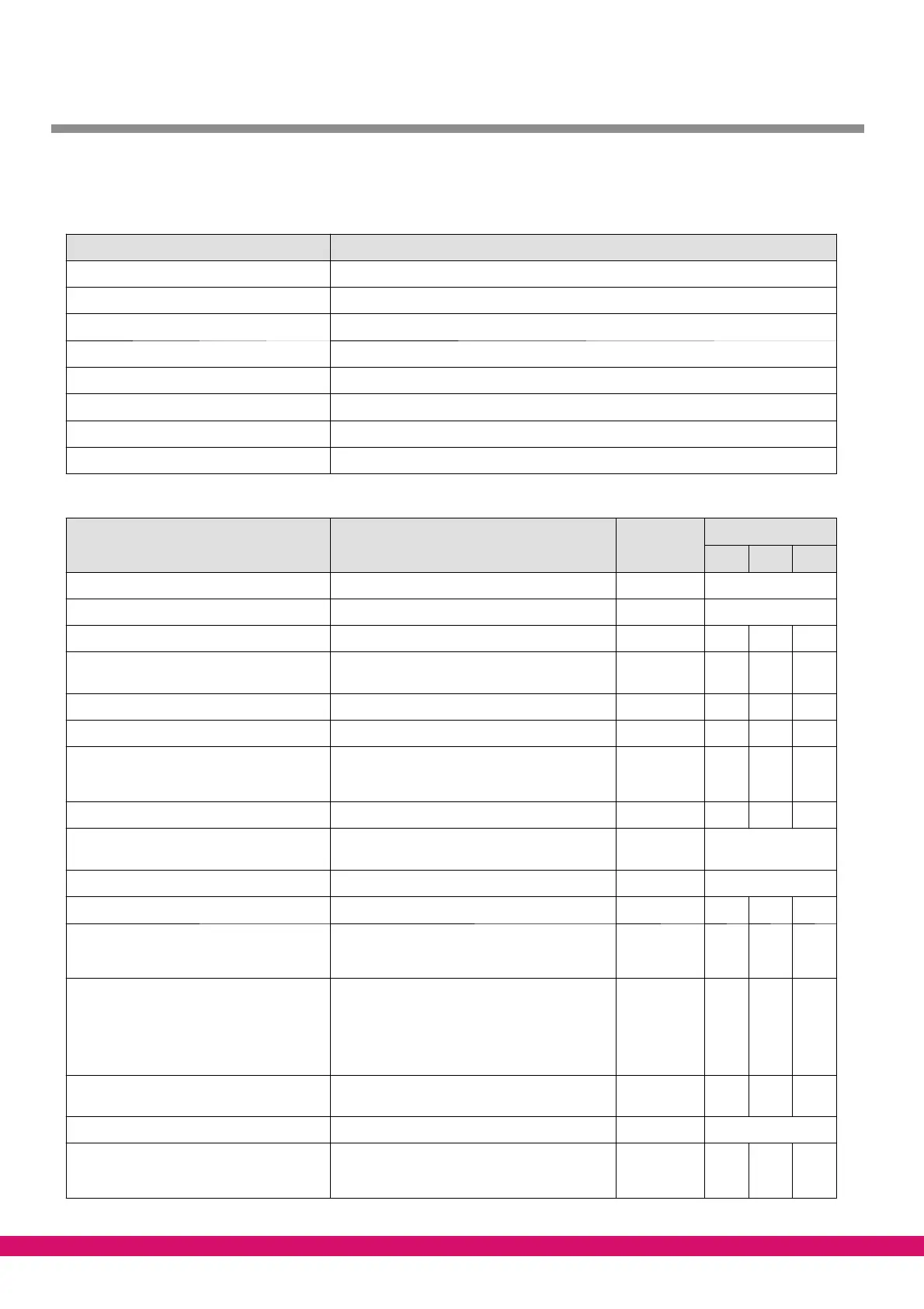
8.1.4 Men u 3 Setpoints
Setpoints POS: XXXXX
1 System config. Move to Menu 3-1
2 Control Move to Menu 3-2
3 Comp. monitor Move to Menu 3-3
4 Liq.level monitor Move to Menu 3-4
5 Ext. alarms Move to Menu 3-5
6 Base load Move to Menu 3-6
7 Messages Move to Menu 3-7
8 D2D Move to Menu 3-8
S Menu 3-1 System config.
Config POS: XXXXX Entry
Default / Dimension
NT LT Dim.
Refrigerant XXXXX→ Select refrigerant → Screen 3-1-a
Sensor match → Matching of pressure transducers → Screen 3-1-b
Oil eq. line X Enable/disable oil equalization YES/NO ↑, ↓ (Y/N) N N -
No. comps. XX Enter number of compressors 1..4/8/12 4/8/
12
4/8/
12
-
No.cap.stages XX Enter number of capacity stages 1 ..3 1 1 -
Mot.cutout C X Enable motor overload cutout YES/NO ↑, ↓ (Y/N) N N -
Oil pr. cutout X Enable disabling of motor overload cutout YES/NO
(only shown when Motor Overload Cutout Comp.
set to Y)
↑, ↓ (Y/N)
Y Y -
Oil/HP-F X Low oil pressure cutout/HP cutout YES/NO ↑, ↓ (Y/N) N N -
Text Oil/HP-F X Select message text to be displayed on compres-
sor oil pressure or high-pressure fault
↑, ↓ (Y/N)
Screen 3-1-c
Enable comp.stages → Show capacity stages → Screen 3-1-d
Emerg. working X Emergency operation YES/NO ↑, ↓ (Y/N) N N -
No.emerg.stages X Number of capacity stages in emergency opera-
tion (only shown when Emergency Operation set
to Y)
1..3/7/11 3/7/11 3/7/11 -
CompOFF.w.LdSh X One complete compressor (with capacity stages)
is shut down at each load shedding stage on load
shed-ding and when system configured with capa-
city-controlled compressors (only shown when
system configured with c apacity controlled com-
pressors: No.CS Ea Comp. > 1)
↑, ↓ (Y/N) N N -
No. cond.stages X Number of condenser stages 1..4/8 /12 4/8/
12
4/8/
12
-
Enable cond.stages → Show condenser stages → Screen 3-1-d
External fan X Enable external fan YES/NO
(only required when using common condenser for
two compressor packs)
↑, ↓ (Y/N) N N -