7 Menu 2-7 - Signal inputs
This button is used to call up the signal and alarm inputs of the system centre. All important
parametersandthestatusofthedigitalinputsaredisplayedthere.
The screen contains the following parameters:
Signal inputs
Message text Message text of the signal input (digital input)
Priority XX Priority of the signal / alarm input
Delay time [Min.] XX Delay time of the signal / alarm in minutes
Quiescent current (low-active) X Alarm is signalled if
- quiescent current = Yes: (signal voltage not present, low-active)
- quiescent current = No: (signal voltage is present, high-active)
Input X
Connection of the input
1)
Status XX Current status of the input:
OK = light grey: no signalling
Wait = yellow: signalling, delay time running,
message = green: no alarm
alarm = red: signalling, alarm / message has been tripped
1)
Designations of the supported modules / inputs:
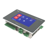
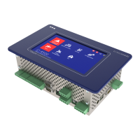
CI 4x00 system centre, internal inputs IN1 / IN2 (terminals A1, A2 / B1, B2)
SIOX1 1st extension module, inputs 1 .. 12
SIOX2 2nd extension module, inputs 1 .. 12
SIOX3 3rd extension module, inputs 1 .. 12
SIOX4 4th extension module, inputs 1 .. 12
DDC1 1st GLT DDC module 1
DDC2 2nd GLT DDC module 2
DDC3 3rd GLT DDC module 3
DDC4 4th GLT DDC module 4
Note: GLT = Building Control System and DDC = Digital Direct Control
The digital signal and alarm inputs are configured using Menu 4-1-2. Further information about the
functions is contained in the chapter Digital inputs.