•
•
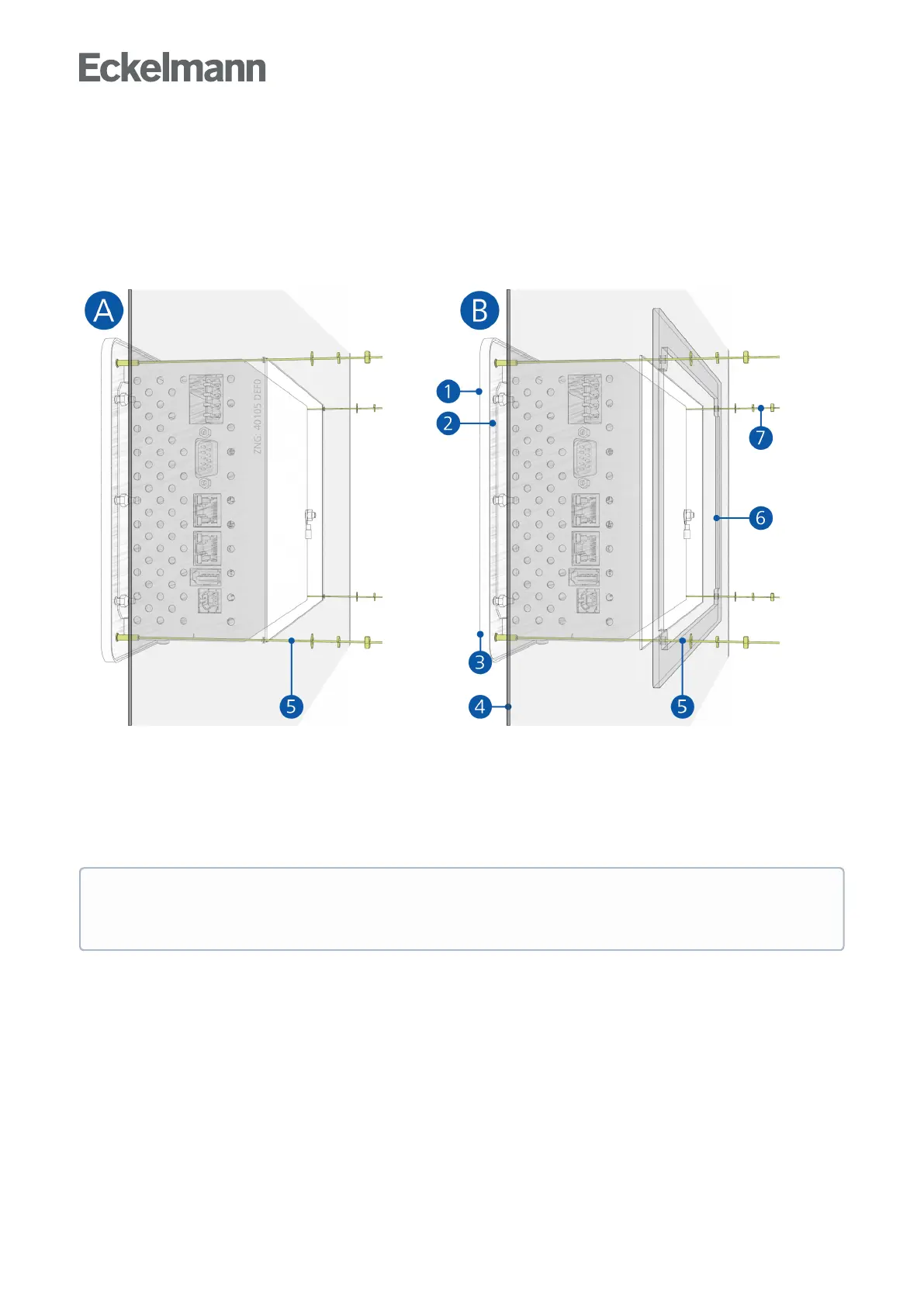
For the installation, the controller must be pushed from the outside through the mounting cut-out in the control
panel (4). The following mounting possibilities can be realised:
Variant A: Complex control panel cut-out with drilled holes, no mounting frame required.
Mounting: The controller is screwed to the control panel using the four M3 stud bolts (3) and associated M3
nuts (7).
Variant B: Simple, rectangular control panel cut-out, mounting frame is required.
Mounting: The controller is screwed to the mounting frame (6) behind it using the four M3 stud bolts (3) and
the associated M3 nuts (7):
(1): Front panel
(2): Rubber seal
(3): 4 x stud bolt M3 x 10 mm
(4): Control panel with mounting cut-out
(5): 4 x drilled hole 4 mm
(6): 1 x mounting frame (part number KGLRAHMEN2, only required for variant B)
(7): 4 x M3: Washer / spring washer / nut
The technical specifications for the dimensions for the mounting cut-outs for the variants A and B are
shown in detail in chapter Control panel cut-out. For details about the wiring, see chapter System
centre and SIOX connection / terminal assignment.