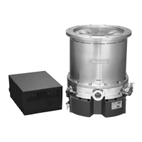
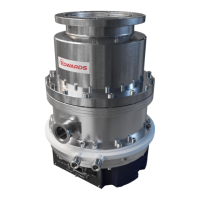
STP-iXA3306 Series Turbomolecular Pump
ILLUSTRATIONS
Figure Title Page
1 STP pump installation warning label 6
2 Hot surface warning label 6
3 Heavy product caution label 7
4 High voltage device caution label 7
5 Rotation instruction label 7
6 Cross sectional view of the STP pump 8
7 External appearance of STP-iXA3306C(V)/iXA3306B(V) 19
8 Label affixing positions 20
9 Space around the STP pump 23
10 Example of lifting the STP pump 25
11 Example of lifting the STP pump (horizontal positioning) 26
12 Jack-up the STP pump 27
13 Control unit bottom face 27
14 Prohibited matter 28
15 STP pump with eyebolts 28
16 Configuration of the STP pump 29
17 Control unit (Front panel) 30
18 Installation of the STP pump to the vacuum equipment 33
19 STP pump installation positions 35
20 Positions of the outlet port on the horizontally
or slanted installed STP pump 35
21 Shape of reduced diameter shank bolts 39
22 Methods of securing the STP pump 39
23 Screw holes for securing the base 40
24 Power cable 41
25 Connecting method of the power cable 42
26 Connecting the purge port 46
27 Positions of the cooling water port 47
28 Baking heater installation position 48
29 Configuration of the TMS 50
30 TMS valve connection 52
31 Pump operation method 1 (contact input) 60
32 Pump operation method 2 (contact input) 60
33 Pump operation method 1 (voltage input) 61
34 Pump operation method 2 (voltage input) 61
35 "ROTATION" LED Indication 63
36 X2 REMOTE connector 64
37 X2 REMOTE input signal pins (contact input) 67
38 X2 REMOTE input signal pins (voltage input) 70
39 X2 REMOTE output signal pins 76
40 Serial port 79
41 X3/X4 connector (D-Sub9) 81
42 RS485 connections 82
43 Grounding example (Both ends grounding) 86
44 Grounding example (single point grounding) 86
45 Example of ring ferrite core installation 87
46 Example of cable installation in metallic duct 87
47 Example of differential signal waveform 88
48 PC to SIM communication 89
49 Block diagram of communication process example 99

 Loading...


