- AB620A5035
8.1 Signal Test Using the Incorporated Control Panel or the V810/V820
8.1.1 Inputs to the control
Select parameter 173 (OFF is displayed).
Control pad on controller: By actuating the keys or switches connected to inputs in1 to in7, the number of
the input actuated appears on the display, e.g. i06. More than one switch and/or key may not be actuated at
the same time.
If more than one key or switch is activated at once, the number of the lowest-numbered input is displayed.
If, for example, in3, in5, in6, in7 are actuated, i03 is displayed.
Note: Checking of positions is described in chapter "Displaying the signal and stop positions".
V810 control panel: The numbers of the inputs in1...in7, in11 (LSM), in12, and in13 appear individually on
the LCD display. Here, too, several switches and/or keys may not be actuated at the same time.
The signals "Light barrier, sensor (IPG... or HSM...), generator pulses 1 and 2, position 1 and 2" can be
checked directly for functionality. The display is carried out using the arrows assigned to keys 2 to 4
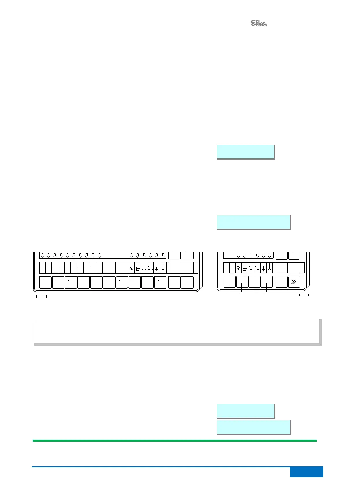
Display example for input 03 on the V810 control panel:
V820 control panel: The numbers of the inputs in1...in7, in11 (LSM), in12, and in13 appear individually on
the LCD display. In addition, the active inputs are displayed by arrows over keys 1 through 6, even if
multiple inputs are actuated at once.
If more than one key or switch is activated at once, the number of the lowest-numbered input is displayed. If,
for example, in3, in5, in6, in7 are actuated, 03 is displayed.
The signals "Light barrier, positions, etc." are displayed by arrows above keys 8, 9, 0.
Display example for input 03 on the V820 control panel:
V820 Control Panel V810 Control Panel
IN3
1
IN2IN1
42 3 5 6
IN8IN7IN6IN5IN4 IN10IN9
987 0
G2
G1
+
TEST
-
KL2460
NOTE
If an input is active with open contact, the corresponding arrow lights up when the contact is open. If an input
is active with closed contact, the corresponding arrow lights up when the contact is closed!
8.1.2 Outputs of control
Select parameter 173.
Select the desired output using the +/- keys.
On the V810 control panel or on the built-in keypad in the control, the >> key is used to turn on the
associated output, if it is connected and working.
On the V820 control panel, instead of the >> key the key lower right, at the outer edge must be pressed.
Display example for backtacking output on the V810 control
panel:
Display example for backtacking output on the V820 control
panel: