- AB620A5035 Instruction Manual
10 Operating Elements and Socket Connectors
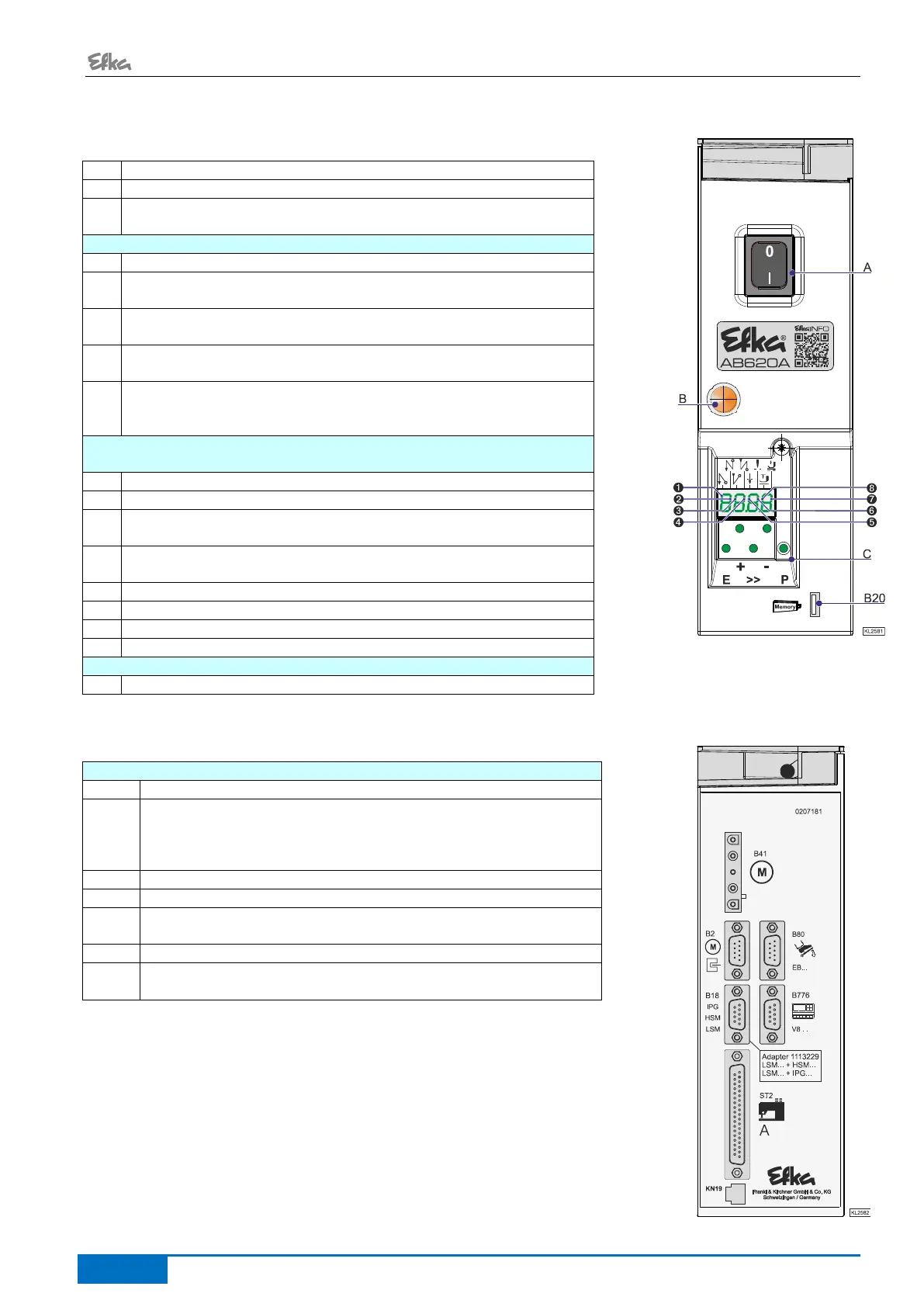
10.1 Positions of the Front Side
Control panel (onboard module)
+ Display (4-digit 7-segment display)
Call or exit programming mode
Start backtack single / double / off
Enter key for modifications in the programming mode
End backtack single / double / off
In the programming mode - increase of the value indicated
Basic position 1 or 2
In programming mode as shift key
Automatic sewing foot lifting at stop in the seam On/Off
Automatic sewing foot lifting after thread trimming On/Off
In the programming mode - decrease of the value indicated
The upper vertical segments of the 4 digit 7 segment display indicate the
switching states of foot lifting and basic position.
Single end backtack
Tape cutter at the start of the seam ON/OFF (mode 7)
Double end backtack
Tape cutter at the seam end ON/OFF (mode 7)
Basic position “needle position 1“
Basic position “needle position 2“
Automatic sewing foot lifting at stop in the seam
Automatic sewing foot lifting after the thread trimming operation
10.2 Positions of the rear side
Light barrier module LSM002
- Hall sensor module HSM001
- Pulse encoder IPG001
(Adapter cord 1113229 in case of multiple assignment)
Socket for inputs and outputs
e. g. solenoids, solenoid valves, displays, keys and switches