E L A N H O M E S Y S T E M S
INSTALLATION MANUAL
Page 26 © ELAN Home Systems 2009 • All rights reserved.
S86A
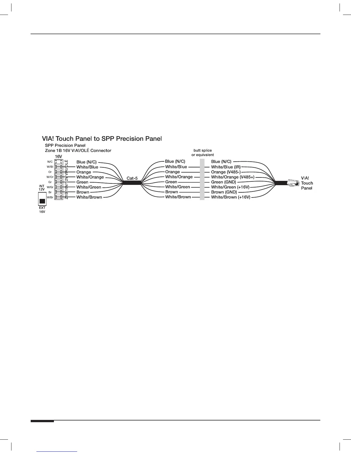
Figure 3-5 shows VIA! Touch Panel connections when the “B” punch-down location is used.
Note: Place the “INT 12V/EXT 16V” switch in the DOWN (“EXT
16V”) position for this application. This allows the external
16VDC power from the PWR1, PWR4, or PWR10 power supply
connected to the front of the SPP to reach the touch panel(s).
Note: Refer to Figure 3-4 for VIA! Valet6.4 connectivity. The “INT
12V/EXT 16V” switch will be in the “EXT 16V” position as
shown in Figure 3-4.
Figure 3-5: VIA! Touch Panel Connections