ADL 2010 / 01 23/57 599 72 63-27
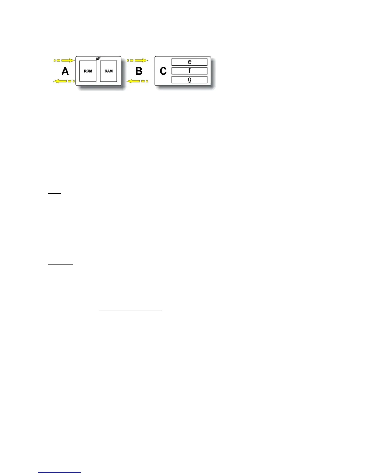
7.1.2 Electronic control memories: general structure
A Asynchronous external serial
port
B Synchronous internal serial port
C EPROM external to the μP
e Power fail and machine status
f Board configuration
g Description of cycle
ROM
This area of the memory contains the "firmware" code comprising the appliance functions:
Ö management of electrical loads (motor, heating unit);
Ö management of sensors (NTC, conductivity sensor, door switch status);
Ö management of the user interface;
Ö management of the serial port;
Ö management of power failures and alarms;
Ö carrying out the drying programme.
In normal appliances this area is of the Read Only Memory type, and therefore cannot be modified.
RAM
This memory contains the variables, that is to say all the dynamic information used during running of the
programme:
Ö Machine status
Ö Cycle selected
Ö Alarms
The memory is deleted every time the power supply stops (in the event of a power failure or when the
appliance is turned off).
The contents of the memory can be read using a computer connected via a DAAS interface.
EEPROM
This memory contains various types of data:
Ö Power fail and machine status, that is to say the information required to start the appliance up again in
the event of a power failure;
Ö Drying cycle configuration: this file describes the various steps in the drying cycle for each family of
appliances (ventilated, condensation, conductivity....);
Ö Machine configuration: data contained in this section of the memory are those that define the
configuration of each individual appliance
and they are interpreted by the operating software. The
following are defined in this file:
- Programmes
- Number and functions of buttons
- LED functions
- Buzzer operation
- Working limits (voltage/frequency)
- Machine identification (PNC + ELC + Serial number)
- Heating unit power
- Preferential direction of rotation of the motor