Commissioning
© Elma Schmidbauer GmbH BA_Elmasteam_8_Vers.07.2016
4 Commissioning
4.1 Installation and Connection Conditions
Retain the original packaging when possible or dispose of it
professionally in accordance with applicable waste disposal
regulations.
You can also return the surplus packaging (at your expense) to the
manufacturer.
Inspect the device after unpacking for possible transport damage
before initial commissioning. The device must not be connected to
the mains supply when damage has been identified. Always
immediately contact your supplier and transport company in such
cases.
Position the device on a stable, level, dry surface which is
insensitive to moisture. The ventilation slits must never be
covered. Retain a distance of at least 10 cm to the walls on the
rear side. Ensure adequate ventilation in the workplace.
The device may only be operated:
• in well-ventilated internal areas
• at an ambient temperature of 5 - 40 º C [41 - 104 °
F] *)
• at a maximum relative humidity of 80% at 31 ° C [87.8 ° F],
decreasing linearly to 50%
relative humidity at 40 ° C [104 ° F] *)
• With a mains power supply when the voltage fluctuations
do not exceed 10% of the nominal value
*) Between 5 - 30 ° C [41-86 ° F], the device is ready for operation at a
relative humidity of up to 80%. At temperatures from 31 - 40 º C [87.8 to
104 ° F], the humidity must decrease proportionally in order to ensure
operational readiness (e.g., at 35 ° C [95 ° F] = 65% humidity at 40 ° C
[104 ° F] = 50% humidity). The device must not be operated at
temperatures above 40 ° C [104 ° F].
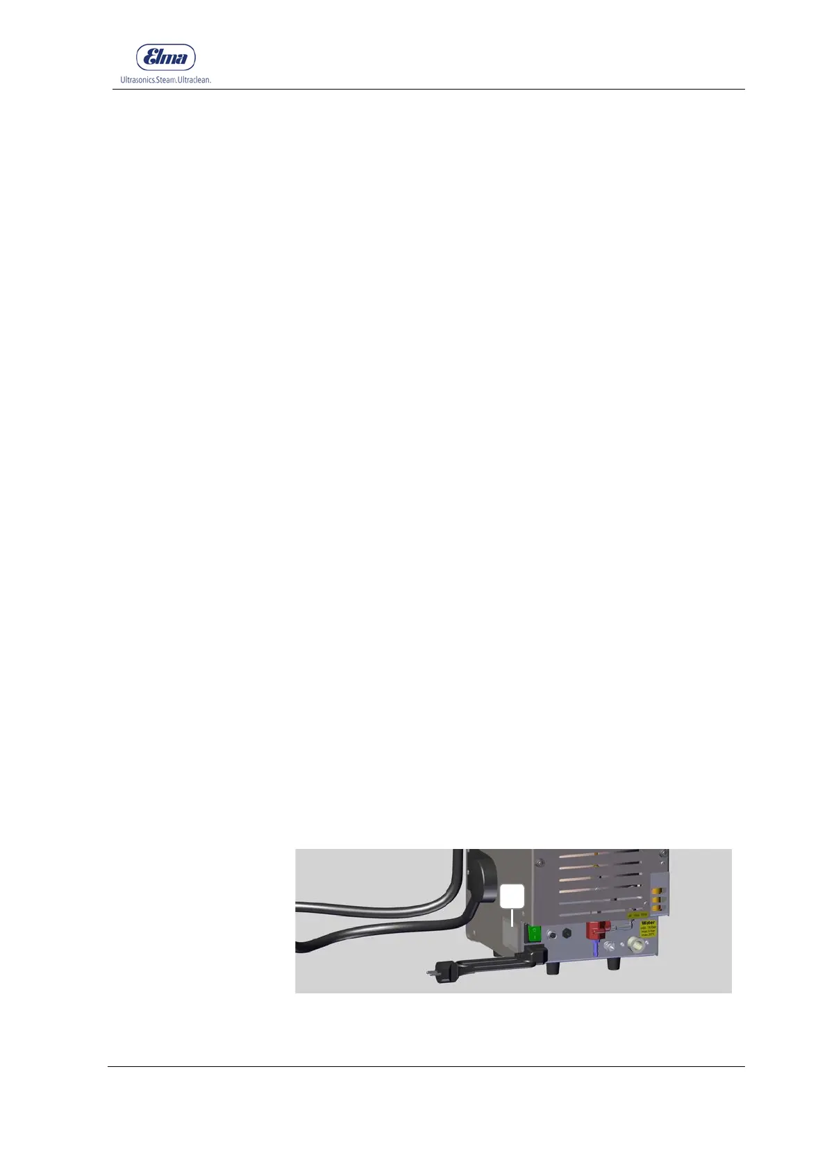
Connect the device to a suitable mains supply plug socket. The
technical data on the nameplate (Figure 4.1-A) must correspond
fully with the available connecting conditions, in particular mains
voltage and current connected load.
Figure 4.1: Nameplate (on the side of the unit)
Inspect for transport
damage