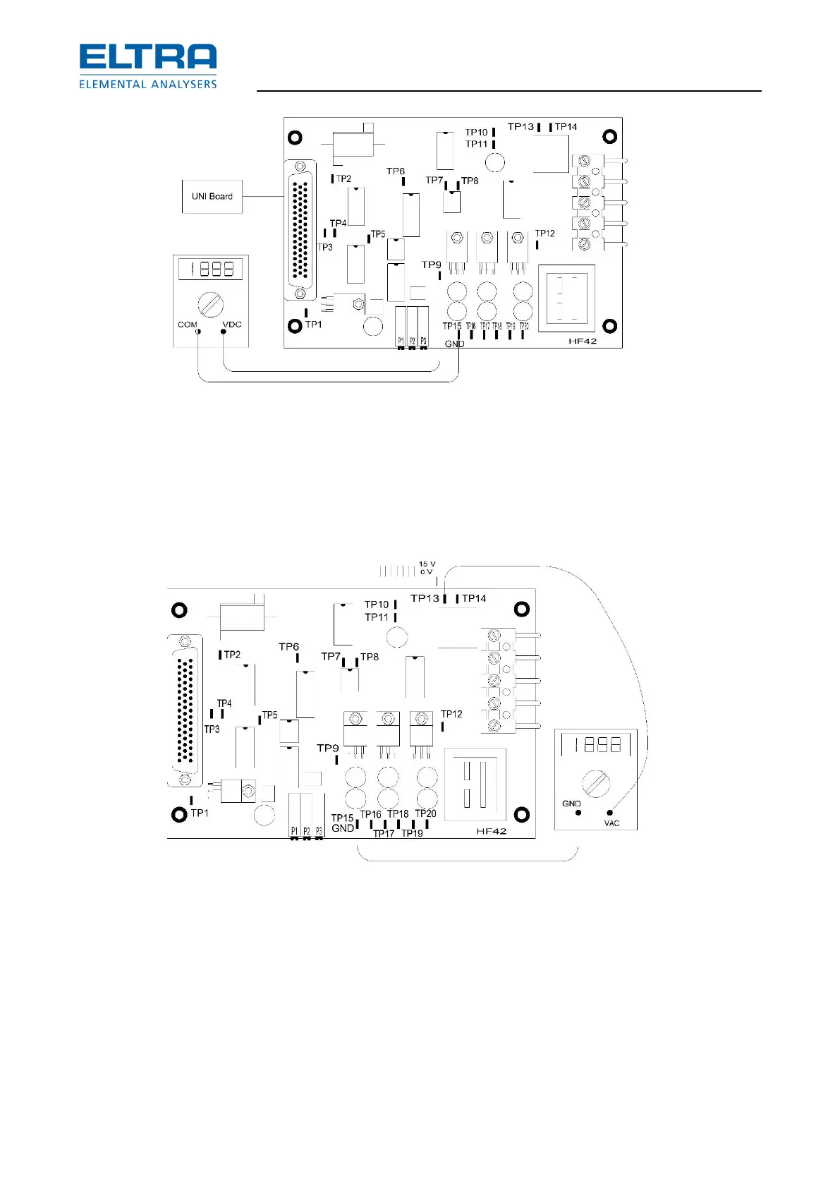
: Measurements on TP9
1. Measurements on TP9
– a signal of about 0.5 V should turn the generator on,
– a signal of about 12 V should turn the generator off.
If 12 V are measured, despite "Analyzing" appearing on the display, then the microcontroller
board is defective or the connection from the HF 42 circuit board, pin 7 is loose.
: TP13 test point
When the command for the generator is received ( 0.5 V DC ), the triac triggering pulses must
appear on the TP13 test point. If there is no oscilloscope available you can test this with a digital
voltmeter. The displayed value depends on what type of digital voltmeter you have. There must
be a voltage increase on TP13, once the word "Analyzing" has appeared on the display, or once
0.5 V are present on TP9. When no voltage increase occurs on TP13 , despite having 0.5 V on
TP9; the HF 42 circuit board is defective.
NOTICE
After replacing the HF 42 board, make sure that the 50 pin plug is properly inserted. It takes a
lot of force to push in 50 pins at once. 50 pin plugs that haven’t been properly inserted are a