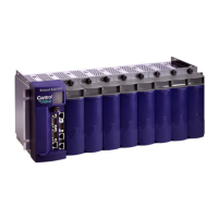
ControlWave Instruction Manual (CI-ControlWave)
IND-6 Index Revised: Nov-2010
2-9. RS-485 Connectors on SCB .2-27
2-10. RS-485 COM3 Port Connector
Pin Assignment........................2-27
2-11. RS-485 COM4 Port Connector
Pin Assignment........................2-28
2-12. RS-485 Network Connections 2-
28
2-13. Ethernet Ports .....................2-29
2-14. Ethernet 10/100Base-T CPU
Module Pin Assignments.........2-30
3-1. DI Module General
Characteristics............................3-8
3-2. DI Module Configurations......3-8
3-3. Jumper Assignments - DI Module
....................................................3-9
3-4. DO Module General
Characteristics..........................3-13
3-5. Isolated DO Module General
Characteristics..........................3-13
3-6. AI Module General
Characteristics..........................3-19
3-7. AI Module Configurations....3-20
3-8. AO Module General
Characteristics..........................3-24
3-9. AO Module Configurations..3-25
3-10. UDI Module General
Characteristics..........................3-29
3-11. UDI Module Configurations...3-
30
3-12. Jumper Assignments – UDI
Module.....................................3-31
3-13. Isolated RTD Input Module
General Characteristics............3-35
3-14. Isolated RTD Input Module
Configurations..........................3-35
3-15. Jumper Assignments - Non-
isolated HSC Module...............3-36
3-16. Isolated LLAI Module General
Characteristics..........................3-39
3-17. Isolated LLAI Module
Configurations..........................3-39
3-18. Jumper Assignments - Isolated
LLAI Module...........................3-39
3-19. LLAI Module Input Accuracy
and Resolution .........................3-43
3-20. LLAI Module RTD Error with
CJC at 25C .............................3-43
4-1. Default Comm Port Settings (by
PCB)...........................................4-2
5-1. LED Assignments on Modules.5-
13
5-2. I/O Field Wiring – Terminal
Block Reference.......................5-21
5-3. Port 80 POST status codes....5-22
5-4. Port 80 Run Time Status Codes5-
24
TB1 Connector
PSSM ...........................................2-16
TB2 Connector
PSSM ...........................................2-12
Temperature
specifications..................................2-2
termination
local................................................3-5
remote ............................................3-6
Troubleshooting........................5-1, 5-12
U
Universal Digital Input Module....... 3-29
Wiring..........................................3-31
Unpacking components......................2-3
Updump
procedure......................................5-32
switch...........................................2-20
Upgrading firmware...........................5-2
V
Vibration
specifications..................................2-2
W
Watchdog
and RPSSM....................................P-5
CPU switch ..................................2-19
Wiring, DC...................................2-16
WINDIAG........................................5-25
Wiring
AI .................................................3-20
AO................................................3-25
Checking......................................5-21
DI ...................................................3-9
 Loading...

