©2020 EMS Ltd. All rights reserved. Page 15 of 80 MK067-0001-99 (Issue 1) 04/11/2020 AJM
WZM connections
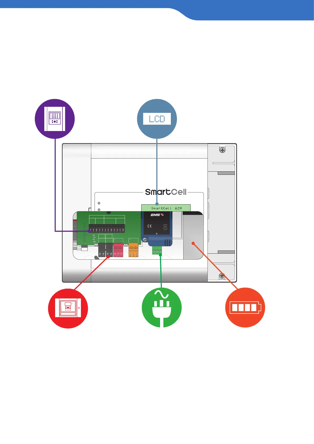
The WZM has a number of connections and features, as detailed below:
INTRODUCTION
FIRE
FAULT
POWER
FUNCTION 1
FUNCTION 2
1
2
3
4
Intelligent Wireless Zone Monitor
EN54-4 UNIVERSAL PSU
SC-60-1000
INPUT: 220-240VAC, 50Hz, 0.3A
OUTPUT: 5.0-8.5VDC, 0.8A MAX
STATUS
FAULT
MAINS / CHARGER FAIL
BATTERY LOW
BATTERY FAIL
START
INPUT
L N E
For additional information refer to TSD042
0359-CPR-00267
15
0359
SLIDE TO
REMOVE
FAU LT
NC C NO
FIRE
NC C NO
ACTIVE ACTIVE
FAULT FAULT
INPUT1 INPUT2
A B A B
EOL
(+) (-) (+) (+) (-) (+) (-) (+) (-) (+) (+) (-)
SOUNDER A
L1 L1 L2 EOL ALARM L1 L1 L2
IN OUT RES IN OUT
ZONE
A
B
C
D
Addressable control panel
connections
48 hr battery back up
Conventional control
panel connections
230 VAC
powered*
80 character
LCD display
* An alternative 24 VDC version WZM is also available for use with a seperate power supply for extended
battery standby time.