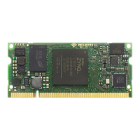
2.5 Top and Bottom Assembly Drawings
2.5.1 Top Assembly Drawing
Figure 6: Module Top Assembly Drawing
2.5.2 Bottom Assembly Drawing
Figure 7: Module Bottom Assembly Drawing
Please note that depending on the hardware revision and configuration, the module may look slightly dif-
ferent than shown in this document.
2.6 Module Footprint
Figure 8 shows the dimensions of the module footprint on the base board.
The maximum component height under the module is dependent on the connector type - refer to Section
2.8 for detailed connector information.
D-0000-424-004 13 / 48 Version 05, 21.08.2018

 Loading...