2.9.8 Analog Inputs
The Zynq-7000 SoC devices provide a dual 12-bit ADC. The auxiliary analog inputs of the SoC device are
connected to the module connector; these I/Os have the abbreviation “AD” followed by the ADC channel in
the signal name.
The two dedicated ADC pins VP and VN are available on the module connector on pins 168 and 170
(FPGA_V_P/N). The ADC can also be used for internal voltage and temperature monitoring. For detailed
information, refer to the Xilinx 7 Series XADC User Guide [19].
The ADC lines are always used differentially; for single-ended applications, the *_N line must be connected
to GND.
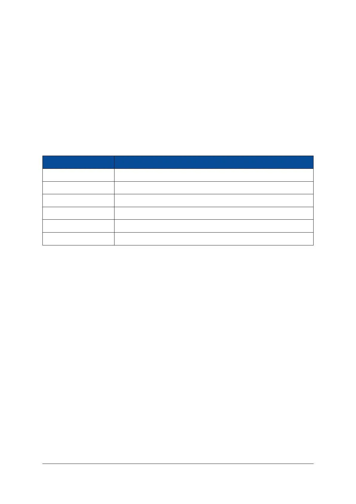
Table 10 presents the ADC Parameters.
Parameter Value
VCC_ADC 1.8 V
GND_ADC 0 V (connected to GND via ferrite)
VREF_ADC 1.25 V
ADC Range 0-1 V
Sampling Rate per ADC 1 MSPS
Total number of channels 17 (1 dedicated channel, 16 auxiliary inputs)
Table 10: ADC Parameters
2.10 Power
2.10.1 Power Generation Overview
The Mars ZX3 SoC module uses a 3.3 - 5.0 V DC power input for generating the on-board supply voltages
(1.0 V, 1.35 V/1.5 V, 1.8 V). These internally-generated voltages are accessible on the module connector. In
addition, a separate 3.3 V power input is used to supply peripherals, such as the Ethernet PHY, QSPI flash,
oscillator, RTC, EEPROM and LEDs.
The Mars ZX3 SoC module can be powered using a single power supply. In this case, the two voltage supply
inputs VCC_MOD and VCC_3V3 must be connected together to a 3.3 V supply. Please refer to Section 2.10.3
for details on the voltage supply inputs.
Table 11 describes the power supplies generated on the module.
D-0000-424-004 20 / 48 Version 05, 21.08.2018

 Loading...

