Warning!
Some of the I/Os are connected to MIO pins and to user logic I/Os in parallel - make sure that at
least one of the two pins is configured to high impedance, and that pull-up or pull-down resistors are
disabled on both if they are not used.
Some of the system pins must be defined as input or high impedance. Please refer to the Mars ZX3
SoC module reference design for details [2].
2.9.4 VREF Usage
I/O standards referenced using VREF can be used on the Mars module connector. The reference voltage
has to be applied to all VREF pins of the respective I/O banks. If a bank is configured to use an I/O standard
that does not need a reference voltage, the VREF pins of this bank on the module connector are available
as user I/O pins.
The VREF pins are listed in the Mars Master Pinout Excel Sheet [11].
Warning!
Use only VREF voltages compliant with the equipped SoC device; any other voltages may damage the
equipped SoC device, as well as other devices on the Mars ZX3 SoC module.
Do not leave a VREF pin floating when the used I/O standard requires a reference voltage, as this may
damage the equipped SoC device, as well as other devices on the Mars ZX3 SoC module.
2.9.5 VCC_IO Usage
The VCC_IO voltages for the I/O banks located on the module connector are configurable by applying the
required voltage to the VCC_IO_B[x], respectively VCC_CFG_[x] pins. All VCC_IO_B[x] or VCC_CFG_[x] pins of
the same bank must be connected to the same voltage.
For compatibility with other Enclustra Mars base boards and modules, it is recommended to use a single
I/O voltage.
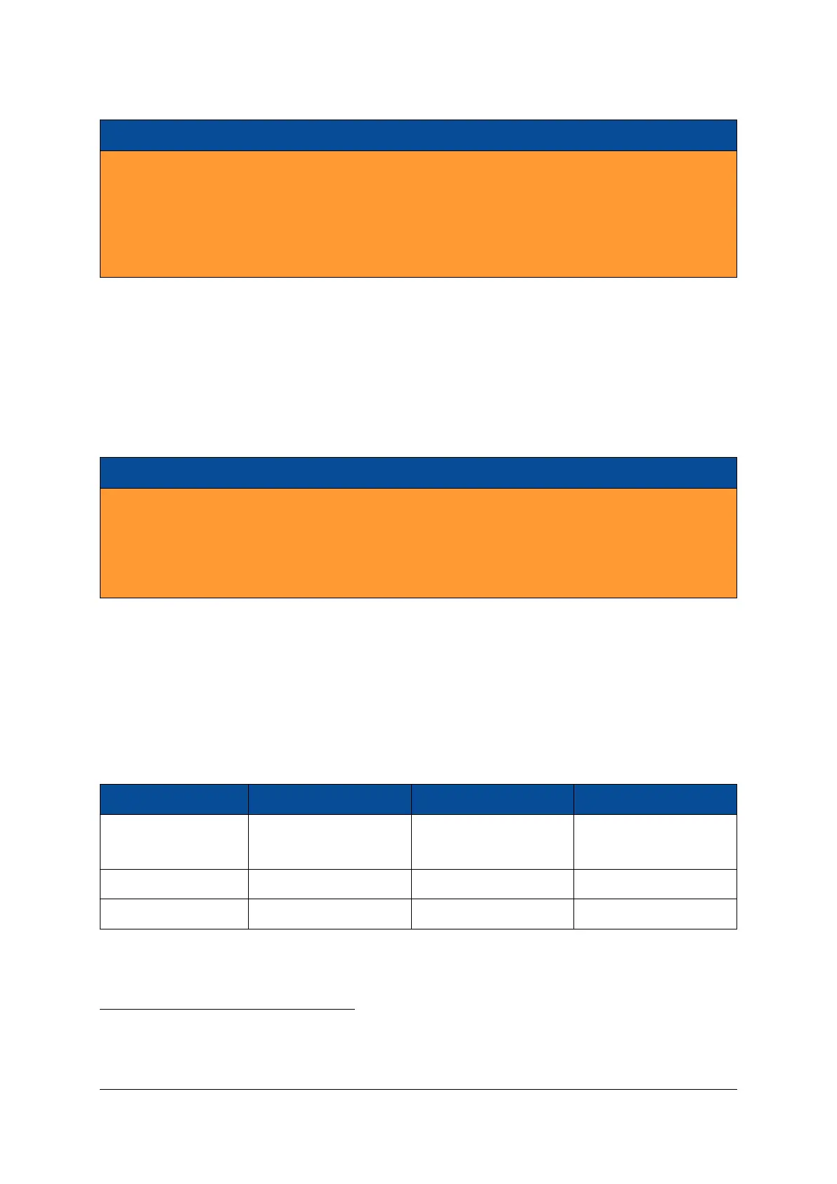
Signal Name SoC Pins Supported Voltages Connector Pins
VCC_CFG_PS_B13_B33 VCCO_13, VCCO_33,
VCC_MIO0, VCC_MIO1
1.8 V
4
, 2.5 V - 3.3 V
5
±5% 137, 146
VCC_IO_B34 VCCO_34 1.8 V - 3.3 V
6
±5% 53, 62, 73
VCC_IO_B35 VCCO_35 1.8 V - 3.3 V
7
±5% 82, 117, 126
Table 7: VCC_IO Pins
4 5 6 7
4
1.8 V support is only available for modules of revision 5 and newer. NAND flash is disabled when VCC_CFG_PS_B13_B33 is 1.8 V.
5
The RGMII Ethernet interface is specified only up to 2.5 V on the MIO pins by Xilinx. Please refer to Section 2.18 for details.
6
I/O bank 34 can run down to 1.2 V if I2C bus access from the PL is not required.
7
I/O bank 35 can run down to 1.2 V, but the FPGA LEDs will be always on in this case.
D-0000-424-004 17 / 48 Version 05, 21.08.2018

 Loading...

