2.9.7 Multiplexed I/O (MIO) Pins
Details on the MIO/EMIO terminology are available in the Zynq-7000 All Programmable SoC Technical Ref-
erence Manual [18].
Some of the MIO pins on the Mars ZX3 SoC module are connected to on-board peripherals, while others
are available as GPIOs; the suggested functions below are for reference only - always verify your MIO pinout
with the Xilinx device handbook.
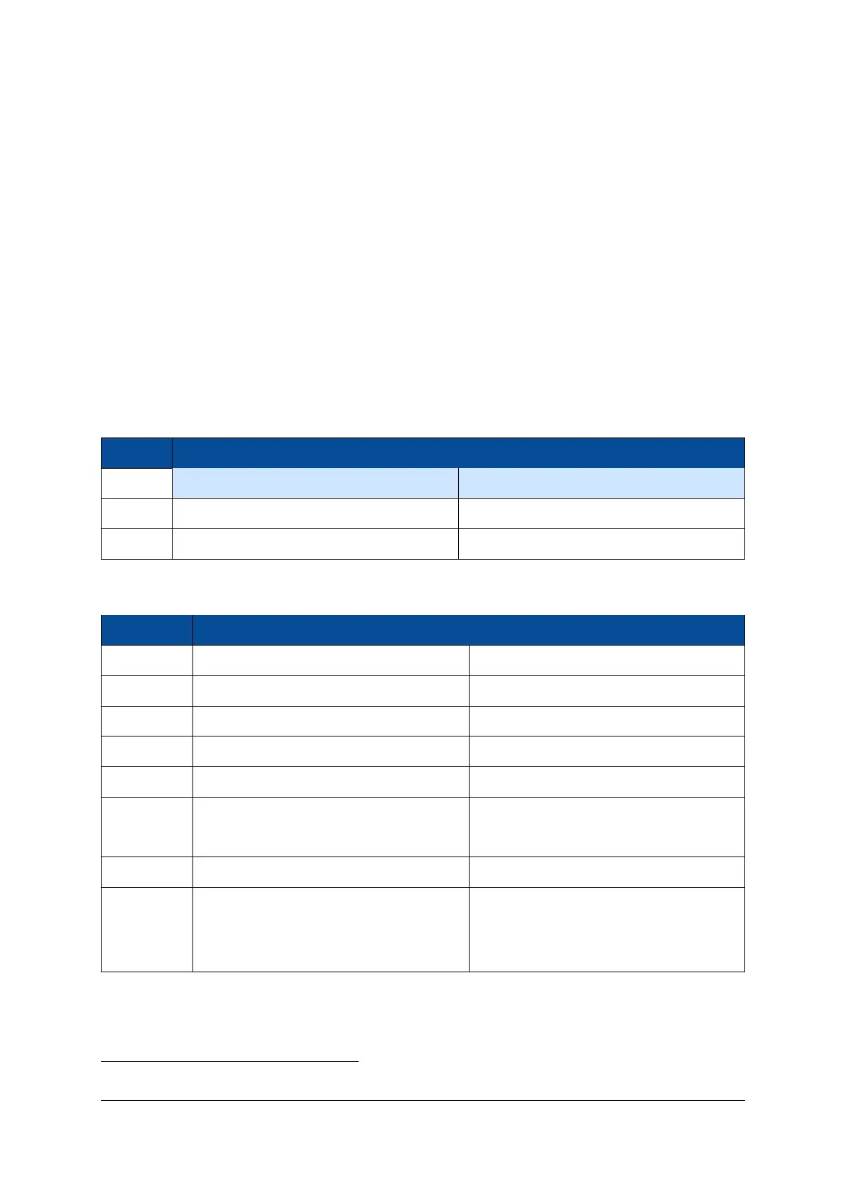
Table 9 gives an overview over the MIO pin connections on the Mars ZX3 SoC module. Only the pins marked
with “user functionality” are available on the module connector.
The MIO pins 52-53 have an external multiplexer that allows the pins to be switched either to the Ethernet
MDIO interface, or to the on-board I2C bus; by default, MDIO is selected. In order to switch to I2C operation,
MIO15 must be pulled low. Please refer to Table 8 for signal assignments.
It is recommended to use EMIO pins for I2C access. However, in situations where Ethernet is not used or
when I2C access is needed before a bitstream is loaded into the FPGA, MIO pins 52-53 may be used for I2C.
MIO Pin Function
MIO15 MDIO select = 0 MDIO select = 1 (default)
MIO52 On-board I2C bus (I2C1.SCL) Ethernet PHY MDC
MIO53 On-board I2C bus (I2C1.SDA) Ethernet PHY MDIO
Table 8: Special MIO Pins
MIO Group Function Connection
0-14 QSPI and NAND flash QSPI/NAND flash
15 MDIO select I2C/MDIO multiplexer selection
16-27 Ethernet Gigabit Ethernet PHY
28-39 USB USB 2.0 OTG PHY
40-45 SD card/user functionality Module connector
46 UART RX
8
/user functionality
Module connector
47 UART TX
8
/user functionality
48-51 User functionality Module connector
Gigabit Ethernet PHY/
52-53 Ethernet MDIO/I2C On-board I2C bus and module connector
via level shifter
Table 9: MIO Pins Connections Overview
8
UART RX is an SoC input; UART TX is an SoC output.
D-0000-424-004 19 / 48 Version 05, 21.08.2018

 Loading...

