or equal to 1.2 V; refer to the level shifter datasheet for details. For VCC_IO_B64 voltages below 1.2 V, the
level shifted signals are not operational.
2.9.3 Differential I/Os
When using differential pairs, a differential impedance of 100 Ω must be matched on the base board, and
the two nets of a differential pair must have the same length.
The information regarding the length of the signal lines from the MPSoC device to the module connector is
available in Mercury+ XU6 SoC Module IO Net Length Excel Sheet [3]. This enables the user to match the
total length of the differential pairs on the base board if required by the application.
Warning!
Please note that the trace length of various signals may change between revisions of the Mercury+ XU6
SoC module. Please use the information provided in the Mercury+ XU6 SoC Module IO Net Length Excel
Sheet [3] to check which signals are affected. The differential signals will still be routed differentially
in subsequent product revisions.
The I/Os in the HD banks (E, F, N, O) can be used only as differential inputs when LVDS/LVPECL standards
are used; LVDS/LVPECL outputs are not supported.
Internal differential termination is not supported for the HD pins; differential input pairs on the module
connector may be terminated by external termination resistors on the base board (close to the module
pins).
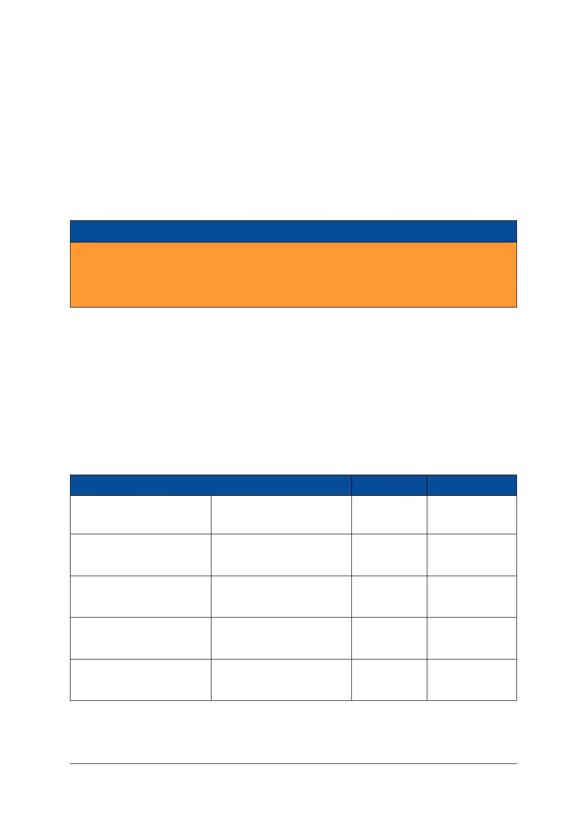
2.9.4 I/O Banks
Table 8 describes the main attributes of the Programmable Logic (PL) and Processing System (PS) I/O banks,
and indicates which peripherals are connected to each I/O bank. All I/O pins within a particular I/O bank
must use the same I/O (VCC_IO) and reference (VREF) voltages.
Bank Connectivity VCC_IO VREF
MGT Bank 224 (available only
on ZU4/ZU5 devices)
Module connector 0.9 V -
Bank 64 Module connector
User selectable User selectable
VCC_IO_B64 0.5 × VCC_IO_B64
Bank 65
Module connector User selectable User selectable
LEDs VCC_IO_B65 0.5 × VCC_IO_B65
Bank 66
Module connector User selectable User selectable
I2C, LEDs VCC_IO_B66 0.5 × VCC_IO_B66
Bank E
Module connector
User selectable
-
25 (ZU2/ZU3) or 45 (ZU4/ZU5) VCC_IO_BE_BF
Continued on next page...
D-0000-464-001 22 / 58 Version 02, 21.07.2021

 Loading...

