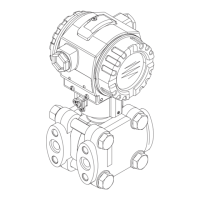
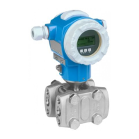
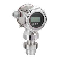
Deltabar S
Endress+Hauser 13
Damping A damping affects all outputs (output signal, display).
• Via on-site display, handheld terminal or PC with operating program, continuous from 0...999 s
• Additionally for HART and PROFIBUS PA: via DIP-switch on the electronic insert, switch position
"on" = set value and "off"
• Factory setting: 2 s
Data of the FOUNDATION
Fieldbus interface
Basic Data
Virtual communication references (VCRs)
Link Settings
Transducer Blocks
Device Type 1009F (hex)
Device Revision 06 (hex)
DD Revision 01 (hex)
CFF Revision 01 (hex)
ITK Version 5.0
ITK-Certification Driver-No. IT054700
Link-Master (LAS) cabable yes
Link Master / Basic Device selectable yes; Default: Basic Devce
Number VCRs 44
Number of Link-Objects in VFD 50
Permanent Entries 44
Client VCRs 0
Server VCRs 5
Source VCRs 8
Sink VCRs 0
Subscriber VCRs 12
Publisher VCRs 19
Slot time 4
Min. Inter PDU delay 12
Max. response delay 10
Block Content Output values
TRD1 Block contains all parameters related to the measurement • Pressure, Flow or Level (Channel 1)
• Process temperatur (Channel 2)
Service Block contains service information • Pressure after damping (Channel 3)
• Pressure drag indicator (Channel 4)
• Counter for max. pressure transgressi-
ons (Channel 5)
Dp Flow Block contains flow and totalizer parameter Totalizer 1 (Channel 6)
Diagnsotic Block contains diagnostiv information Error code via DI channels (channel 0 to
6)
Display Block contains parameters to configure the local display no output values
 Loading...


