THIS DOCUMENT CONTAINS CONFIDENTIAL INFORMATION PROPRIETARY TO ENERGATE INC. NO PART OF ITS CONTENTS MAY BE DISCLOSED OR CONVEYED TO,
USED BY, OR COPIED TO A THIRD PARTY WITHOUT PRIOR WRITTEN CONSENT BY ENERGATE INC. PRINTED COPIES WILL BE CONSIDERED UNCONTROLLED.
AW000873-G 37
Step 7 – Pass the five wire cable through a convenient access hole in the equipment.
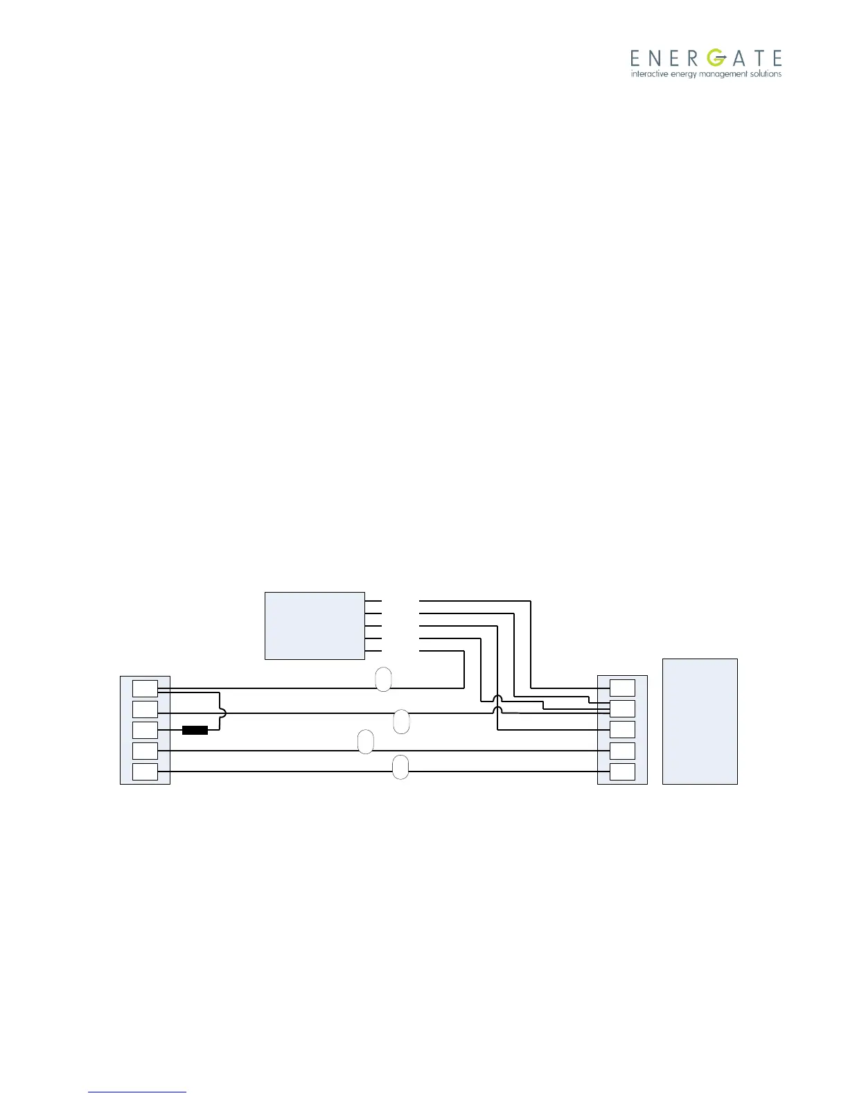
Step 8 – The wire labelled G must be spliced to the Auxiliary Switch cable using a wire cap as follows:
Wire labelled G to the Auxiliary Switch WHITE wire.
Step 9 – Connect the blue and green wires from the Auxiliary Switch to the equipment as follows:
BLUE wire to the equipment C terminal.
GREEN wire to the equipment G terminal.
Step 10 – Connect the remaining two wires from the Auxiliary Switch and the wire labelled R from the thermostat as
follows:
Auxiliary Switch YELLOW and RED wires and the wire labelled R to the equipment R terminal.
Step 11 – Restore power to the equipment and follow the equipment configuration instructions in the thermostat user
manual for testing.
Step 12 - Record the serial number of the unit, name and address of the owner, and make and model of the heating
and/or cooling equipment. Install the Connection Diagram sticker (AW000785) on a visible place on the HVAC cabinet
or on the wall close to the Auxiliary Switch.
Note: If the old thermostat has no connection to G, but instead to W, then connect the W wire to C at the thermostat
and the signal coupler between W and C at the thermostat location. At the equipment location, connect the Auxiliary
Switch green wire to W instead of G at the equipment. Connect the Auxiliary Switch White wire to the W wire with a
wire cap at the equipment location.
8.1.2 Running a Common (Ground) Wire
If a common wire is not available at the thermostat and the installer determines that it is more efficient to run a fresh
common wire from the HVAC equipment transformer or simply does not have an auxiliary switch available, take the
following precautions:
Use the common or ground wire of the transformer of the HVAC equipment.
Auxiliary
Switch
Single Transformer
Connection Schematic
WHITE
YELLOW
RED
GREEN
BLUE
R
G
W
Y
C
R
G
W
Y
C
Thermostat
HVAC Equipment
Signal Coupler
Legend
R – 24VAC
C – Common
W – Heating
Y – Cooling
G – Fan
Example for single stage
Heat/Cool system.
G
R
W
Y
Labels per steps 1 and 6.