THIS DOCUMENT CONTAINS CONFIDENTIAL INFORMATION PROPRIETARY TO ENERGATE INC. NO PART OF ITS CONTENTS MAY BE DISCLOSED OR CONVEYED TO,
USED BY, OR COPIED TO A THIRD PARTY WITHOUT PRIOR WRITTEN CONSENT BY ENERGATE INC. PRINTED COPIES WILL BE CONSIDERED UNCONTROLLED.
AW000873-G 40
Step 6 – Before disconnecting wires at the equipment, label them according to which equipment terminal block they
are connected, verifying these labels match the labels attached in step 1.
Step 7 – Pass the five wire cable from the Auxiliary Switch through a convenient access hole in the equipment.
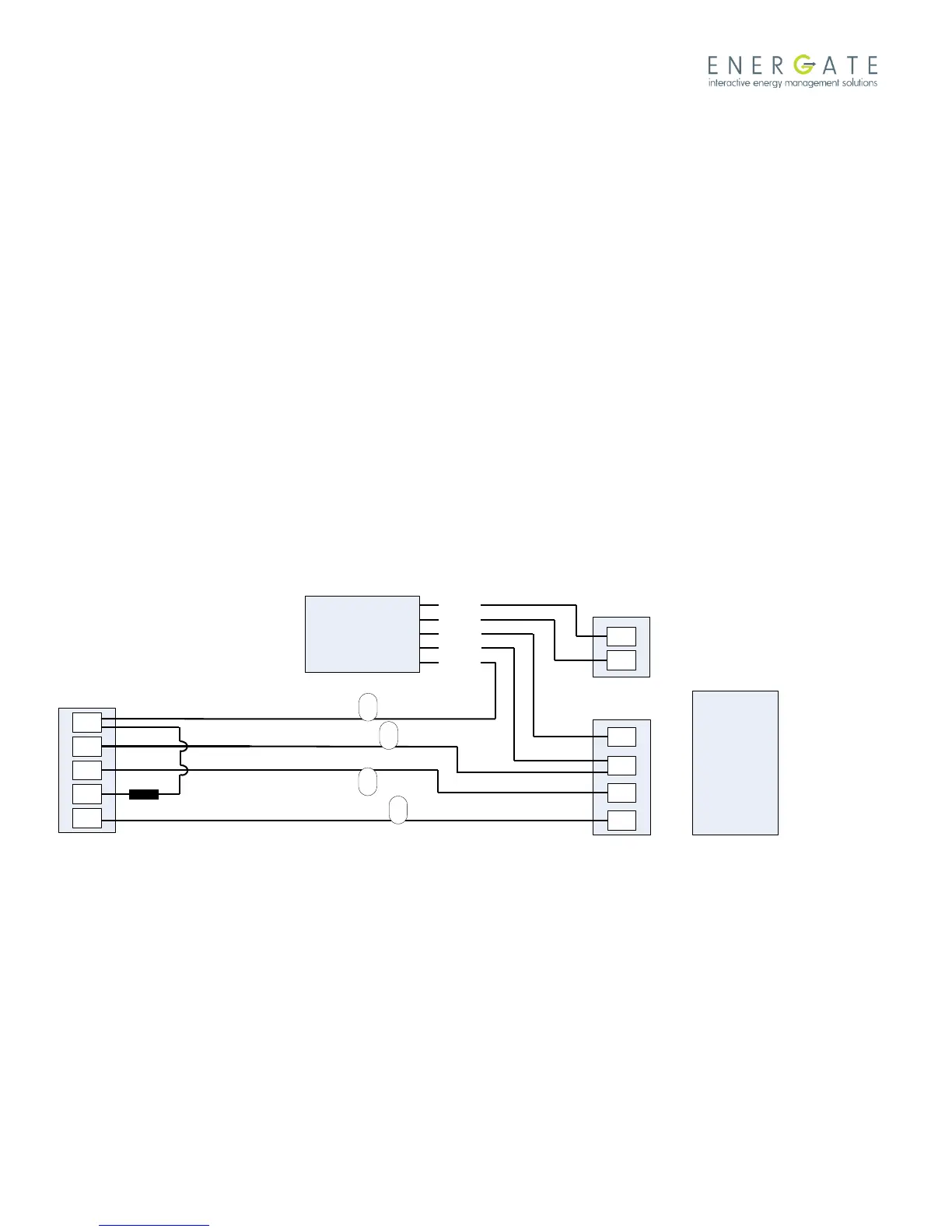
Step 8 – The wires labelled RC and W must be spliced to the Auxiliary Switch cable and equipment as follows:
Wire labelled RC and Auxiliary Switch YELLOW wire both to the Cooling equipment RC terminal.
Wire labelled W to the Auxiliary Switch WHITE wire.
Step 9 – Connect the three remaining wires from the Auxiliary Switch to the furnace as follows:
RED wire to the Heating equipment RH terminal.
GREEN wire to the Heating equipment W terminal.
BLUE wire to the Cooling equipment C terminal.
Step 10 – Restore power to the equipment and follow the equipment configuration instructions in the thermostat user
manual for testing.
Step 11 - Record the serial number of the unit, name and address of the owner, and make and model of the heating
and/or cooling equipment. Install the Connection Diagram sticker (AW000785) on a visible place on the HVAC cabinet
or on the wall close to the Auxiliary Switch.
Auxiliary
Switch
Dual Transformer
Connection Schematic
WHITE
YELLOW
RED
GREEN
BLUE
R
G
W
Y
C
RC
G
Y
C
Thermostat
Cooling Equipment
RH
W
Heating Equipment
Signal Coupler
Legend
R – 24VAC
C – Common
W – Heating
Y – Cooling
G – Fan
Example for single stage
Heat/Cool system.
W
RC
G
Y
Labels per steps 1 and 6.