Installation and Operation Manual - DustEx Installation
Doc.-ID: COM_OXI_Dust_11022020 1
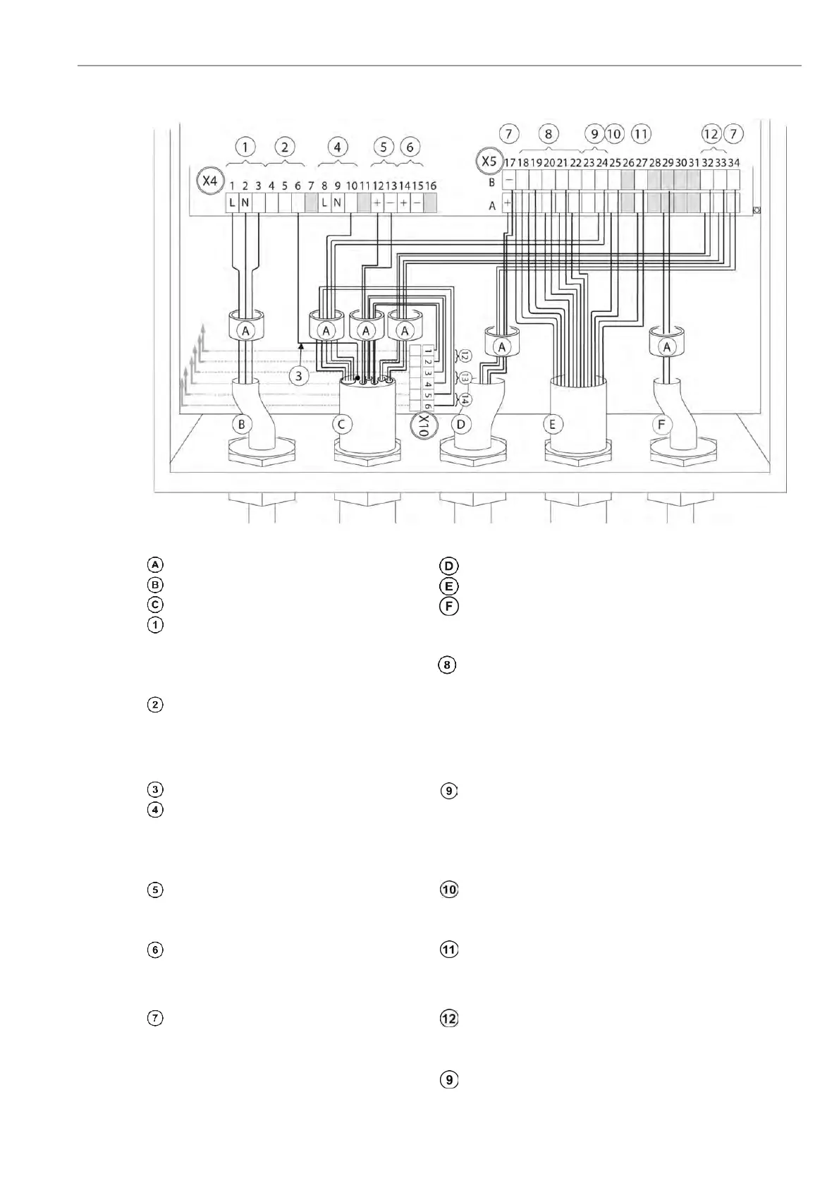
2.5 Wiring Diagram of the Electronic Unit
Figure 7 - Wiring diagram of the Electronic Unit
Ferrite sleeves (Enclosed)
nalogue output cable (customer)
Power supply cable (customer) Status signal cable (customer)
Probe signal cable Optional pressure transmitter analogue input cable
(OXITEC 5000 DustEx only) (customer)
Internal Power supply
1 L phase
2 N neutral wire Relay contacts for status signals - Potential free
3 PE protection earth 18 A/B Maintenance
1
The output voltage of
these contacts (4…6)
always have the same
voltage as on the
ower supply input on
contacts (1…3)
Grounding 19 A/B System Error
4 PE protection earth 20 A/B Output A O
2
measuring range
5 PE protection earth 21 A/B Limit Alarm 1 (O
2
)
6 FE functional earth 22 A/B Limit Alarm 2 (COe)
Shielding Probe solenoid valve
Power supply probe heater (115V) 23 A
Internal Power supply for
probe solenoid valve (115VAC)
8 L black 23 B
9 N blue 24A L grey
10 PE green/yellow 24B N grey/blue
O
2
sensor signal Measuring Range O
2
(12..24V DC - Ext. supply)
12 + brown 25A +
13 - brown/white 25B -
Thermocouple (O
2
sensor) Calibration release (12..24V DC – Ext. supply)
14 + green 27A +
15 - white 27B -
Analogue outputs (active 4-20mA) COe sensor (COMTEC 6000 DustEx only)
17A + O
2
32A
COe
sensor
white/red 2
17B - O
2
32B
white/red 1
34A + COe
33A
COe
sensor
red 4
34B
-
COe
33B red 3