Installation Installation and Operation Manual - COMTEC
®
/
OXITEC
®
DustEx
6 Doc.-ID: COM_OXI_Dust_11022020
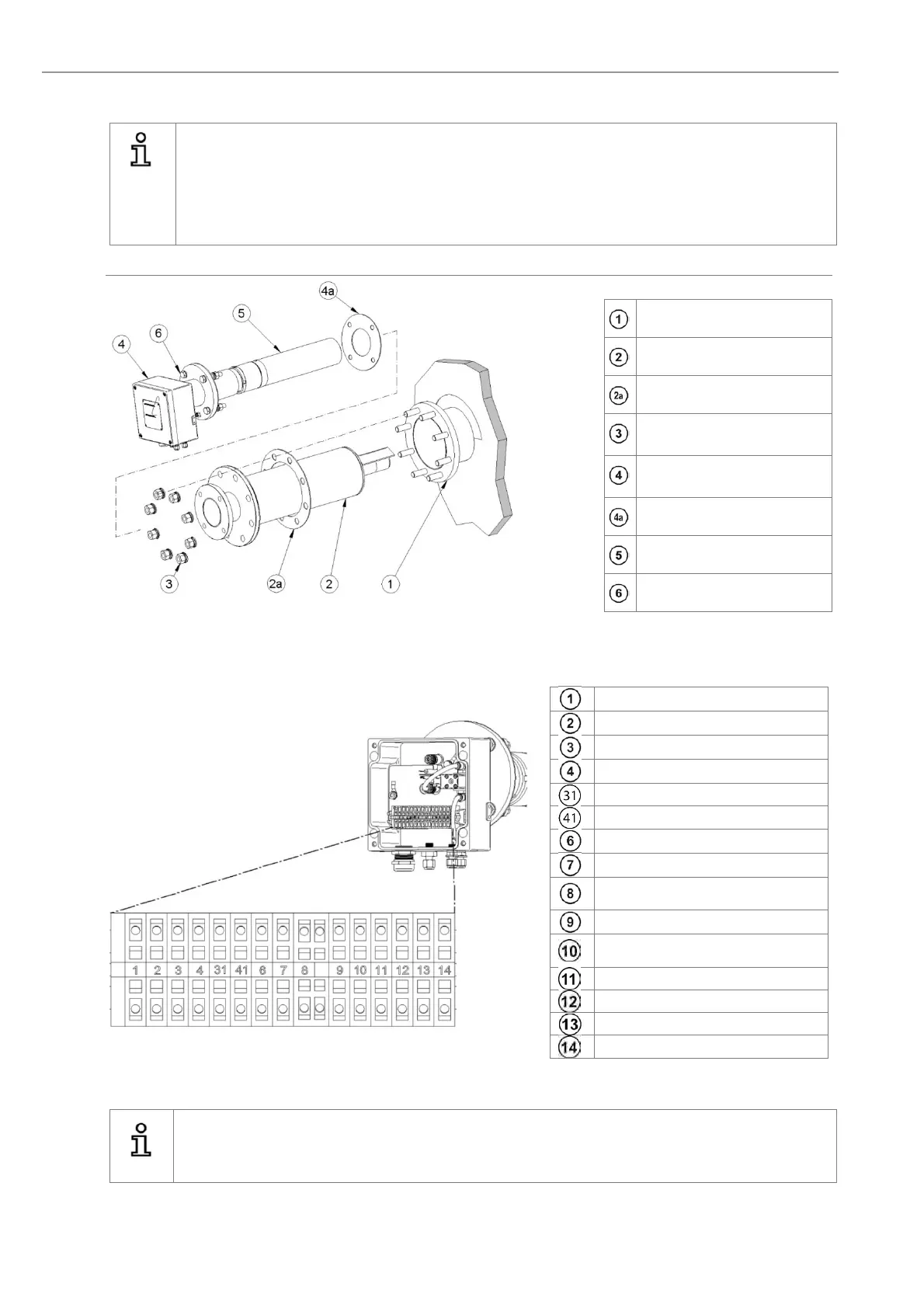
2.11 Mounting of the Probe
Info
For the installation of the probe, use only new and undamaged gaskets. Tighten the nuts firmly to
guarantee the tightness of the flange connection. The probe parts outside of the duct wall must be
insulated (or heated if necessary), to prevent its temperature from dropping below the acid dew point.
Never leave the probe unheated in the running process for a longer period of time!
Electrical heaters are available from ENOTEC. The bolts of the probe flange must always remain
accessible.
Counter plate welded gastight
Probe protection tube
Probe protection tube gasket
Nuts, washers and lock
washers
Measuring probe KES600X
DustEx
Probe flange gasket
Filter head
Probe flange
Figure 12 - Mounting of the probe with protection tube
2.12 Electrical Connections of the Probe
- mV O2 sensor (white-brown)
+ mV O2 sensor cell (brown)
+ mV thermocouple 1 (green)
- mV thermocouple 1 (white)
+ mV thermocouple 2 (green)
- mV thermocouple 2 (white)
L 115VAC heater (black)
N 115VAC heater (blue)
PE Protection earth (green
yellow)
L 115VAC solenoid valve (grey)
N 115VAC solenoid valve (grey-
blue)
COe Sensor (white red1)
COe Sensor (white red2)
COe Sensor heater (red1)
COe Sensor heater (red2)
Figure 13 - Terminal connections in the connections box
Info
The supply voltage to the solenoid valve at the probe is internally connected to 115V AC supplied by the
SME5 electronic unit.