Installation and Operation Manual - DustEx Initial Operation
Doc.-ID: COM_OXI_Dust_11022020 3
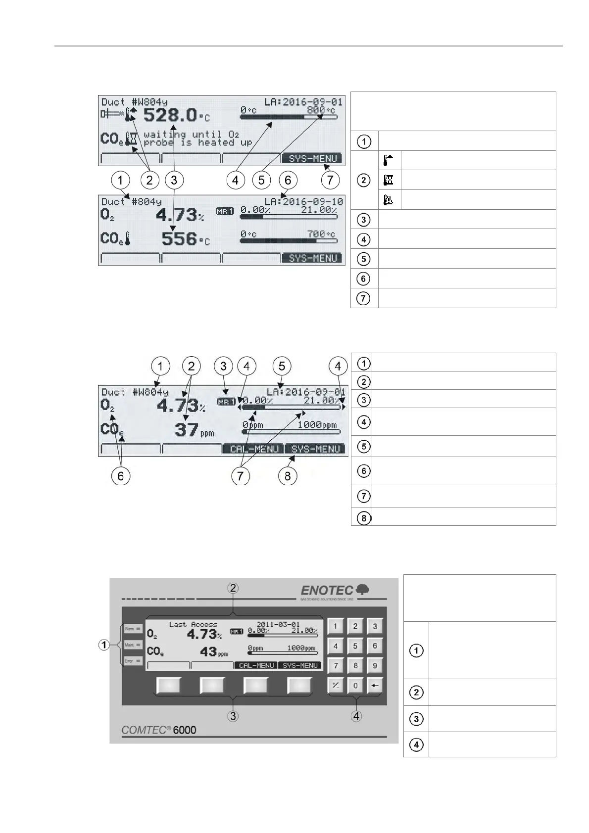
3.3 Display - Probe Heating Phase
Figure 19 - O
2
and COe sensor heating phase
The probe heating phase begins with the heating
up of the O
2
sensor. After this is concluded, the
COe sensor begins its heating up phase.
TAG number
Rising probe temperature
(or) waiting period
(or) heater error
Current temperature
Analogue temperature bar
Set point probe temperature
Last access
Softkey title: e.g. System menu
3.4 Display - Measuring Mode
Figure 20 - Display Measuring mode
TAG number
Measured values
Active measuring range
Blinking indicators showing under or over
measuring range
Last access
Measured components (COe only
COMTEC)
Limit alarm indicators
min-Alarm /
max-Alarm *
Softkey titles
* Only if the limit alarms are switched on and the limits are within the set measuring range.
3.5 Keypad and Display
The controls and display of the
analyzer are housed in the
electronic unit and are
comprised of:
Three LED indicators
depicting active status
reports for limit alarms,
maintenance and system
faults
Graphic enabled, back-lit
display
Four soft keys with varying
layout
Numeric number bloc
Figure 21 - Keypad and display (OXITEC and COMTEC may differ)