5050 CONTROL UNIT
Technical Manual & Cabling Instructions
19.10.2012
Epec Oy reserves all rights for improvements without prior notice
Epec Oy Postiosoite/Postal address Puhelin/Phone Fax Internet
Tiedekatu 6 PL/P.O.Box 194 +358-(0)20-7608 111 +358-(0)20-7608 110 www.epec.fi
FIN-60320 Seinäjoki FIN-60101 Seinäjoki, Finland
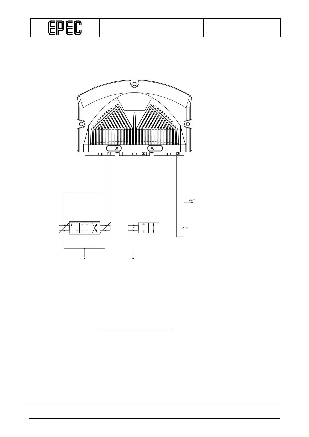
The following figure shows three different ways to connect open circuit loop (from the control
unit’s point of view):
• Proportional valve (on the left)
• ON/OFF valve
• ON/OFF switch (on the right)
• All sensors and encoders must be wired according to the closed-loop principle, i.e. the
power for the sensors and encoders is supplied by the module they are connected to.
This way, it is possible to avoid potential harmful differences, so the MOSFET driven
output power switching operates properly.
When designing the sensor and encoder connections, observe single-point grounding. Each
control unit connector has several GND pins which should be used.
Refer to section
Power supply pins and limitations for accurate pin allocation of connectors.