EPS NEXUS Manual V1.5.2 EN WWW.EPSBV.EU 14
3.4 Calibration cover
*Important*
From 06-03-23, the procedure for 'calibration cover' has been changed3.4.1 Introductie
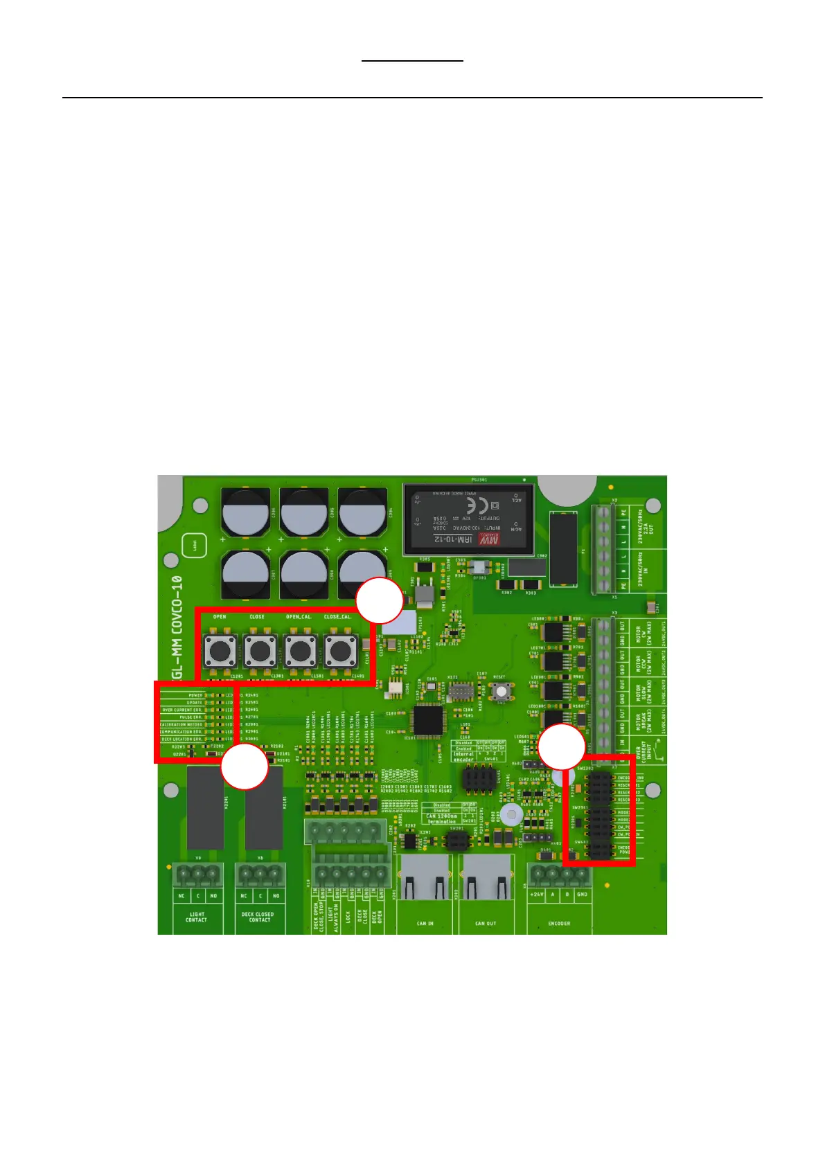
The following is a brief explanation of the PCBA.
1. From left to right, the buttons are as follows
a) OPEN, this button allows you to open the deck during calibration. Keep the button pressed for this purpose. In normal
operation, this button can be used to select the open position.
b) CLOSE, this button allows you to close the deck during calibration. Keep the button pressed for this purpose. In normal
operation, this button can be used to select the close position.
c) OPEN.CAL, with this button the open position can be calibrated. This button is used only in the calibration procedure.
d) CLOS.CAL, allows calibrating the close position. This button is used only in the calibration procedure.
2. The LEDs each indicate a status.
a) Power LED. Power supply is correct
b) Update LED. An update is required/available when the light is on.
c) Over current ERR. An overcurrent has been measured when the light is on or the emergency stop button has been pressed.
d) Pulse ERR. When this light is on, the system indicates that pulses were expected but not measured. Check the motor and/or
pulse sensor.
e) Calibration needed. Calibration of the deck is needed.
f) Com ERR. N/A
g) Deck location ERR. The system has failed during a deck movement and needs a new calibration.
3. Mode selection switches.
a) Use only the mode selection switches during the calibration procedure.