Setup & Operation 14. Option Slots
RC700 / RC700-A Rev.23 113
14.8.7 Input Circuit (EUROMAP67 Board)
Input Voltage Range : + 12 to 24 V ±10 %
ON Voltage : + 10.8 V (MIN.)
OFF Voltage : + 5 V (MAX.)
Input Current : 10 mA TYP / + 24 V input
14.8.8 Output Circuit (EUROMAP67 Board)
Rated Output Voltage : + 12 V to 24 V ± 10 %
Maximum Output Current : TYP 100 mA / 1 output
Output Driver : PhotoMOS relay
On-resistance (average) : 23.5Ω or less
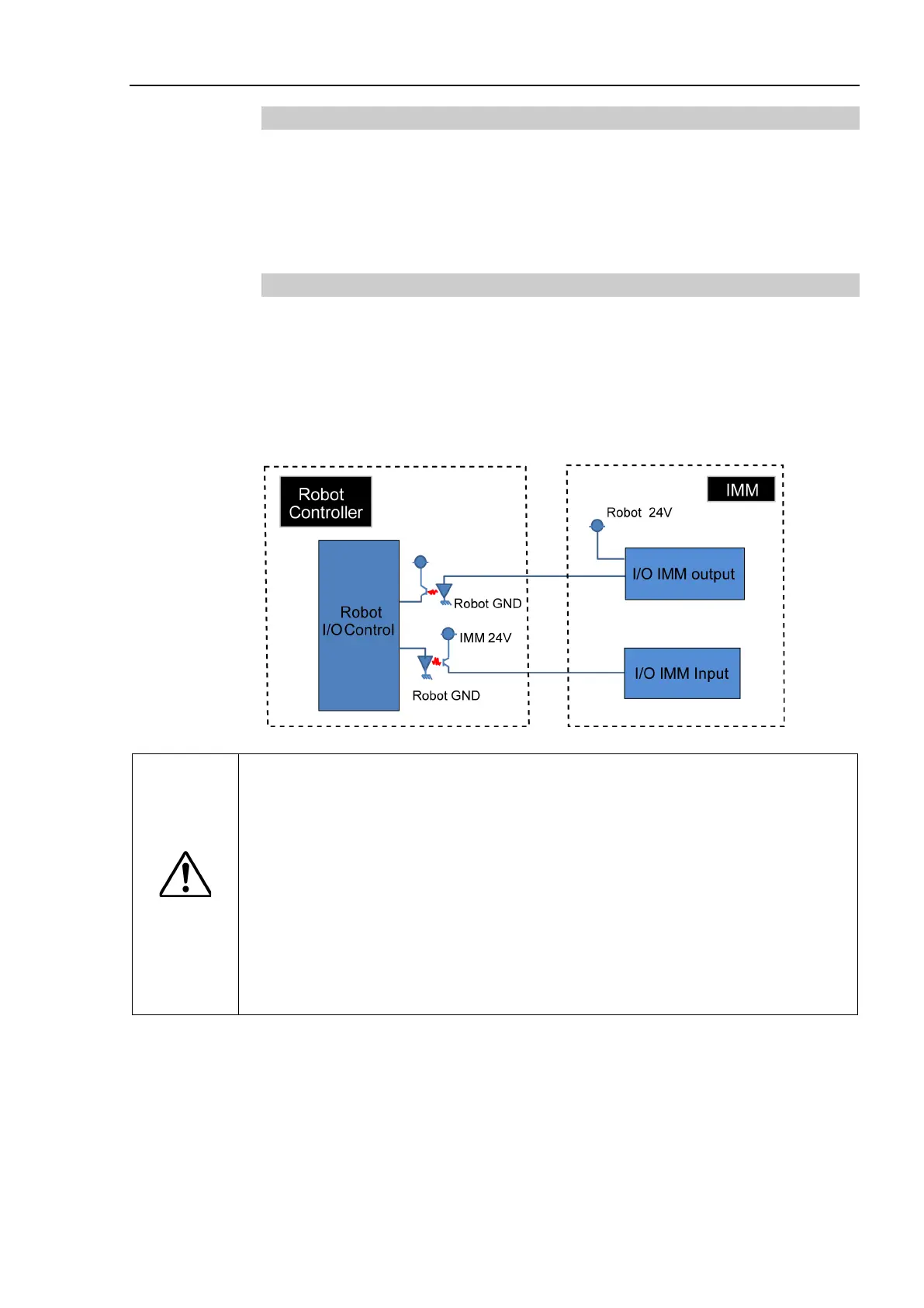
EUROMAP67 board input/output circuit overview
CAUTION
Input/output circuits do not have a built-
in protection circuit to prevent short
circuits or reverse connections.
Take care to avoid wiring mistakes.
Wiring mistakes may damage board parts and
prevent the robot system from
functioning properly.
Do not use a higher than rated voltage or current.
Doing so may damage board parts and prevent the robot system from functioning
properly.
Note that the I/O logic for controlling the IMM will vary
machine. Confirm the proper logic to use before creating programs.