Setup & Operation 11. I/O Connector
RC700 / RC700-A Rev.23 61
11. I/O Connector
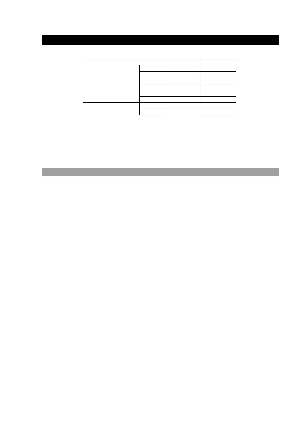
The I/O connector is for connecting your input/output equipment to the system.
Control Unit
Drive Unit 1
Drive Unit 2
Drive Unit 3
Refer to Setup & Operation 14.2. Expansion I/O board.
For cable wiring, refer to the Setup & Operation 3.5 Noise Countermeasures in order to
prevent noise.
Remote function is initially assigned to both input and output from 0 to 7. For further
details, refer to Setup & Operation 12. I/O Remote Settings.
11.1 Input Circuit
Input Voltage Range : +12 to 24 V ±10%
ON Voltage : +10.8 V (min.)
OFF Voltage : +5 V (max.)
Input Current : 10 mA (TYP) at +24 V input
Two types of wiring are available for use with the two-way photo coupler in the input
circuit.