Safety 2. Part Names and Functions
18 RC700 / RC700-A Rev.23
2.1 LED and Seven-segment LED
2.1.1 LED and Seven-segment LED Display
There are four LEDs and a four-digit seven-segment LED display located on the front
panel of the Controller.
LED : LED (TEST, TEACH, AUTO, PROGRAM) turns ON according to the
current operation mode (TEST, TEACH, Auto, Program).
Seven-segment : Indicates the line number and Controller status (error number, warning
number, Emergency Stop or Safeguard status).
From turning ON the Controller to completing startup
LED : All four LEDs blink.
Seven-segment : All four LED digits turn OFF the lights.
After Controller Startup
LED : LED (TEST, TEACH, AUTO, PROGRAM) turns ON according to the
current operation mode (TEST, TEACH, Auto, Program).
Seven-segment : Display changes according to the Controller status.
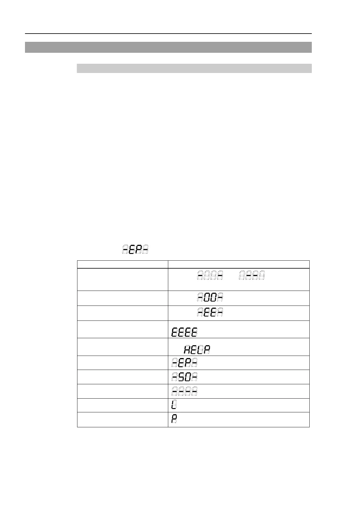
When several Controller statuses occurred at one time, the status
indicated earlier on the following table is displayed. For an example,
when both Emergency Stop and Safeguard statuses occurred at one time,
is displayed.
Execute Controller status
storage function
Displays and
repeatedly.
Complete Controller status
storage to USB memory
Displays (for 2 seconds)
Failure of Controller status
storage to USB memory
Displays (for 2 seconds)
Displays four-digit error number (0.5 sec) and
(0.5 sec) repeatedly.
*1
Displays four-digit warning number (0.5 sec)
and (0.5 sec) repeatedly.
*1
Emergency Stop
Blink
Safety Door
Blink
READY
Blink
START
line number
Blink
PAUSE
line number
Blink
*1 For error numbers, refer to EPSON RC+ 7.0 SPEL+ Language Reference, or Online
Help.
*2 In initial status, execution line of task number 1 is displayed in three-digit.
Use Ton statement to change the displayed task number.
For details, refer to EPSON RC+ 7.0 SPEL+ Language Reference, or Online Help.