Setup & Operation 13. R-I/O Connector
78 RC700 / RC700-A Rev.23
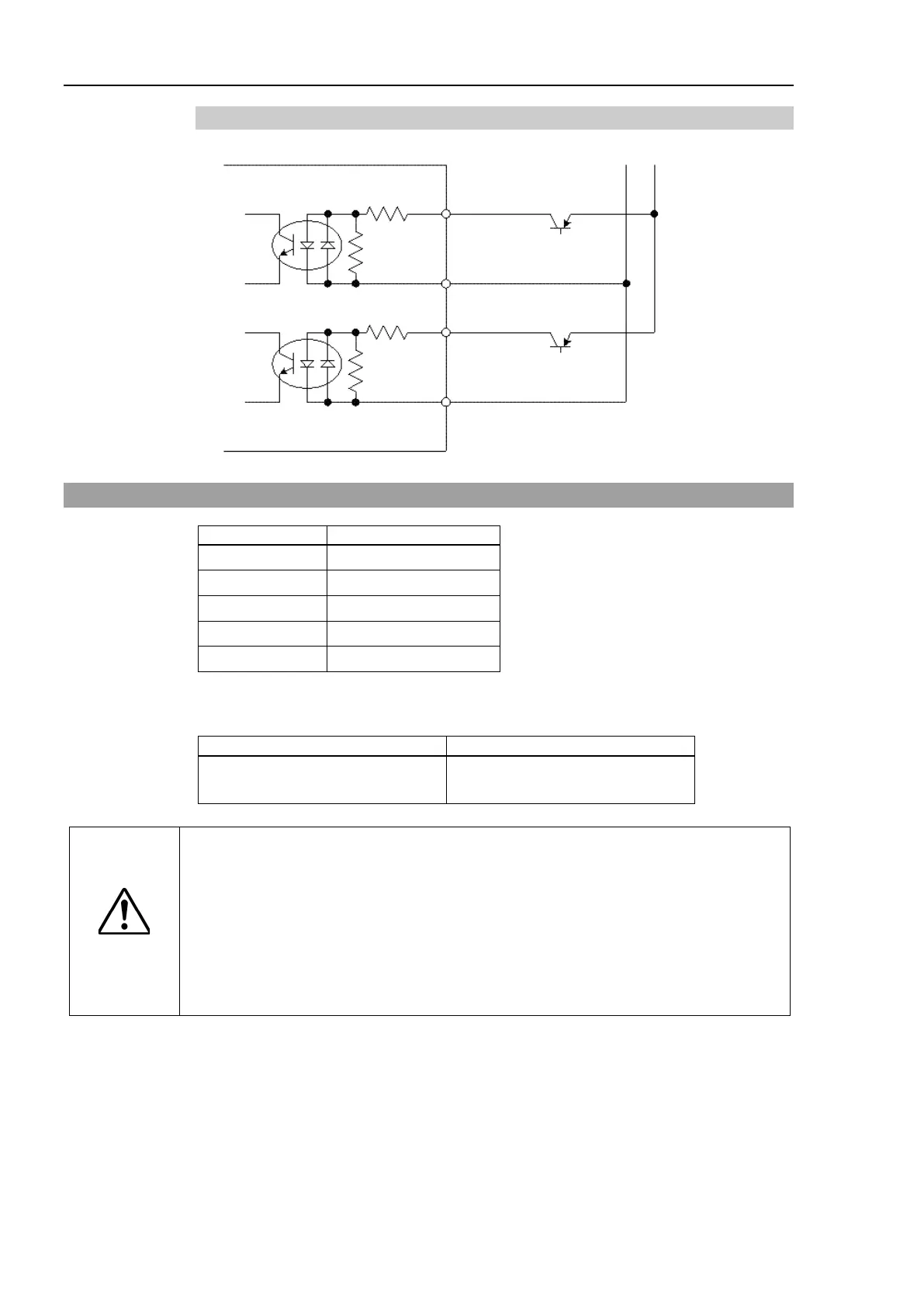
Typical Input Circuit Application 2
13.2 Pin Assignments
10 INPUT No24-2
11 INPUT No25-1
1 to 8, 13 to 15* Not Used
* For the pins 1 to 8 and 13 to 15, do not connect anything.
R-I/O Connector (Controller side)
D-sub 15 male pin
Mounting style #4 - 40
CAUTION
When using R-I/O connector, be careful of the following points. If you
R-
I/O connector without meeting the necessary conditions, it may cause the
system failure and/or safety problems.
- Use a shielded cable and route the cables as far from the surrounding
noise sources as possible.
For details, refer to Setup & Operation: 3.5 Noise Countermeasures.
- Make sure to check the cable routing before turning on the power supply.