EasyManuals Logo

Epson RC700-A User Manual

Epson RC700-A
316 pages
To Next Page IconTo Next Page
To Previous Page IconTo Previous Page
Page #129 background imageLoading...
Page #129 background image
Setup & Operation 14. Option Slots
RC700 / RC700-A Rev.23 117
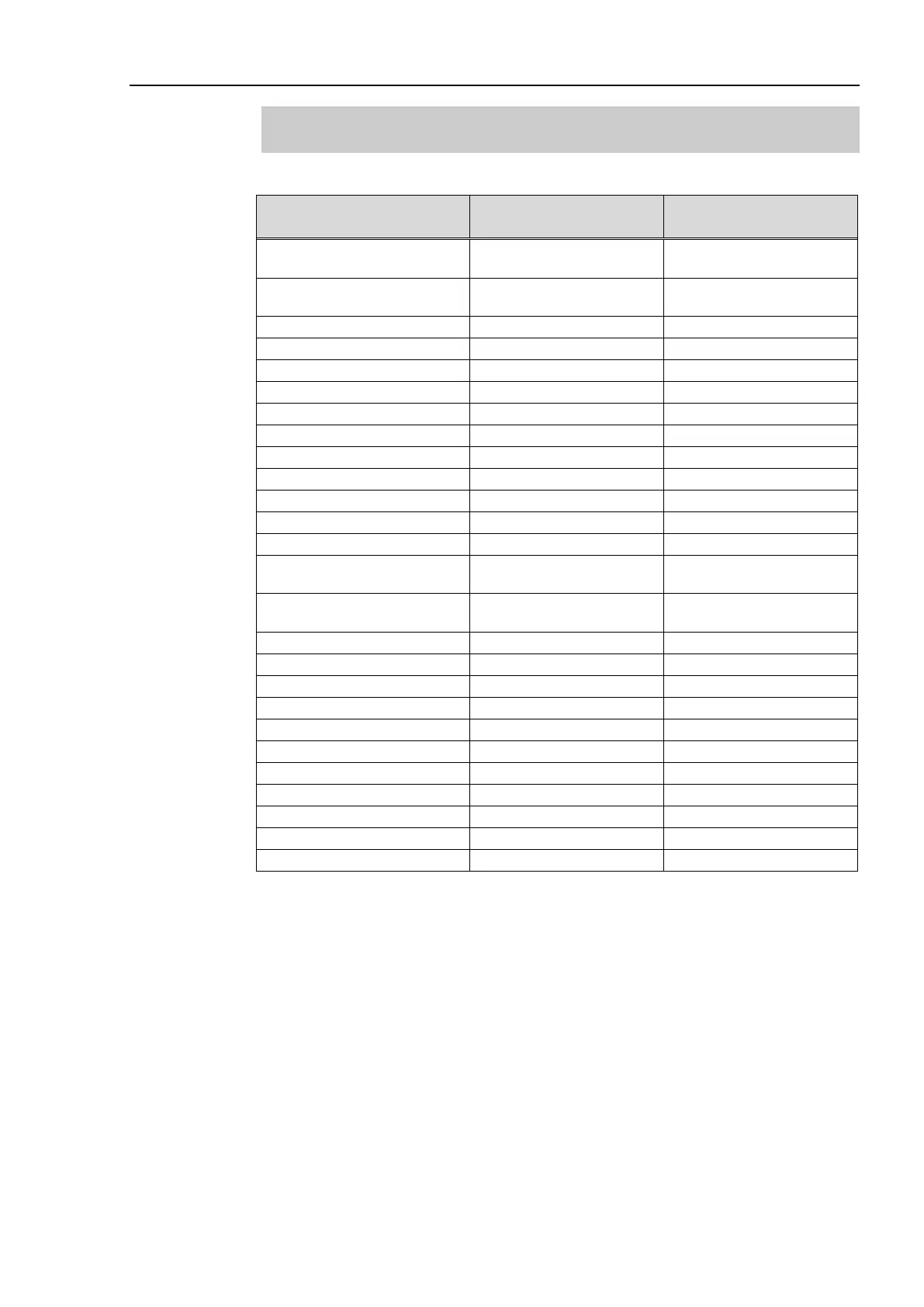
14.8.11 Emergency stop connecter Pin Assignments
(EUROMAP67 Board)
Emergency stop connecter (CN2) Pin Assignment table of the EUROMAP67 board.
Emergency stop connecter
(CN2) Pin No.
Signal Name Function
1 ESW11
Emergency Stop switch
contact
2 ESW12
Emergency Stop switch
contact
3
ESTOP1+
Emergency Stop circuit 1+
4
ESTOP1-
Emergency Stop circuit 1-
5
Not Used
-
6
Not Used
-
7
SD11
Safety Door input 1
8
SD12
Safety Door input 1
9
24V
24V output
10
24V
24V output
11
24VGND
24VGND output
12
24VGND
24VGND output
13
Not Used
-
14 ESW21
Emergency Stop switch
contact
15 ESW22
Emergency Stop switch
contact
16
ESTOP2+
Emergency Stop circuit 2+
17
ESTOP2-
Emergency Stop circuit 2-
18
SDLATCH1
Safety Door Latch Release
19
SDLATCH2
Safety Door Latch Release
20
SD21
Safety Door input 2
21
SD22
Safety Door input 2
22
24V
24V output
23
24V
24V output
24
24VGND
24VGND output
25
24VGND
24VGND output
26
Not Used
-

Table of Contents

Other manuals for Epson RC700-A

Questions and Answers:

Question and Answer IconNeed help?

Do you have a question about the Epson RC700-A and is the answer not in the manual?

Epson RC700-A Specifications

General IconGeneral
BrandEpson
ModelRC700-A
CategoryController
LanguageEnglish

Related product manuals