EasyManuals Logo

Epson RC700-A User Manual

Epson RC700-A
316 pages
To Next Page IconTo Next Page
To Previous Page IconTo Previous Page
Page #128 background imageLoading...
Page #128 background image
Setup & Operation 14. Option Slots
116 RC700 / RC700-A Rev.23
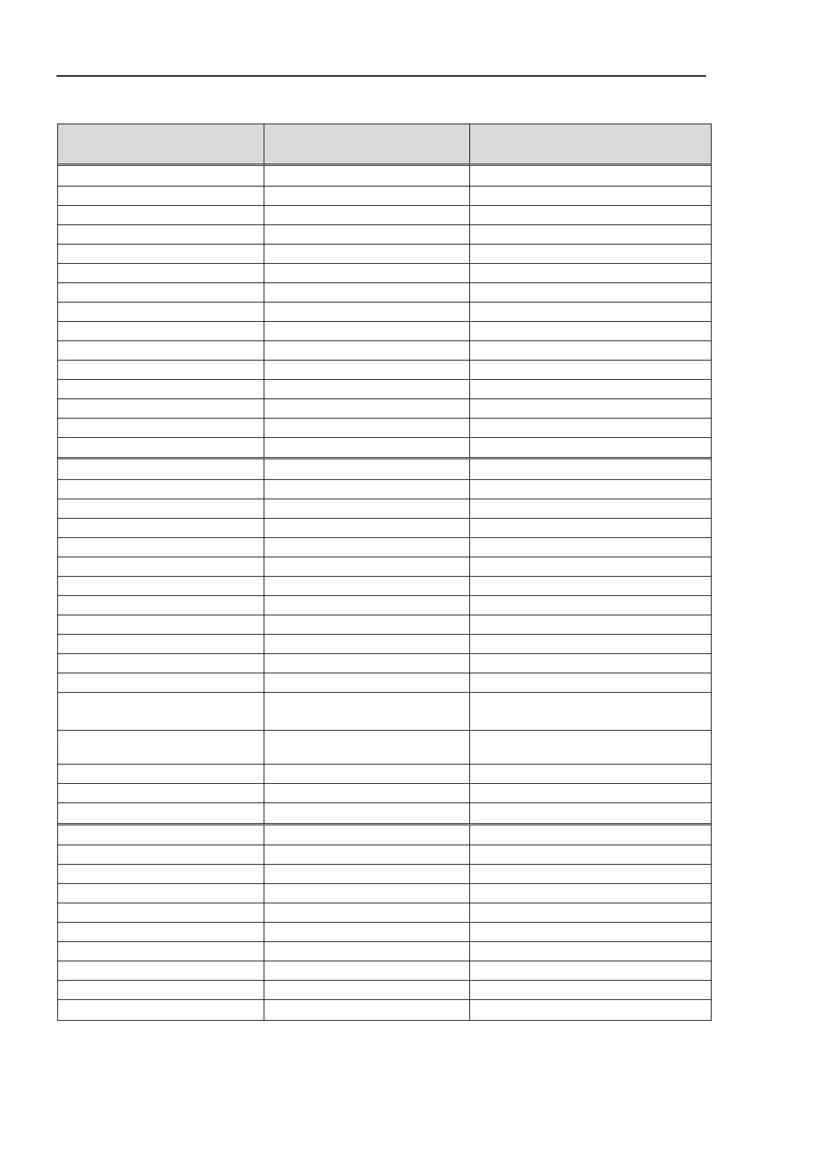
I/O Pin Assignment table of the 2nd EUROMAP67 board.
Signal Name
D-Sub connecter (CN1)
Pin No.
EUROMAP67 connecter (CN4)
Pin No.
Input No.224
33
ZA5
(*1)
Input No.225
32
ZA6
(*1)
Input No.226
50
ZA7
(*1)
Input No.227
49
ZA8
(*1)
Input No.228
48
ZB2
(*1)
Input No.229
47
ZB3
(*1)
Input No.230
31
ZB4
(*1)
Input No.231
30
ZB5
(*1)
Input No.232
15
ZB6
(*1)
Input No.233
14
ZB7
(*1)
Input No.234
46
ZB8
(*1)
Input No.235
45
ZC5
(*1)
Input No.236
29
ZC6
(*1)
Input No.237
28
ZC7
(*1)
Input No.238
13
ZC8
(*1)
Output No.224
41
A6
(*1)
Output No.225
7
A7
(*1)
Output No.226
8
A8
(*1)
Output No.227
24
B2
(*1)
Output No.228
25
B3
(*1)
Output No.229
42
B4
(*1)
Output No.230
43
B5
(*1)
Output No.231
9
B6
(*1)
Output No.232
10
B7
(*1)
Output No.233
26
B8
(*1)
Output No.234
27
C6
(*1)
Output No.235
11
C7
(*1)
Output No.236 4/3
A3/C3
(ModuleArea+/ModuleArea-)
Output No.237
(Not Used)
37/36
A4/C4
(Not Used)
Output No.238
12
C8
(*1)
Output No.239
40
A5
(*1)
Output No.240
44
C5
(*1)
24V (IMM)
1
A9
(*1)
GND (IMM)
2
C9
(*1)
Emergency1 (IMM)
39/38
ZA1/ZC1
Emergency2 (IMM)
21/20
ZA2/ZC2
Safety1 (IMM)
6/5
ZA3/ZC3
Safety2 (IMM)
23/22
ZA4/ZC4
24V (Robot)
17
ZA9
GND (Robot)
16
ZC9
Emergency1 (Robot)
35/34
A1/C1
Emergency2 (Robot)
19/18
A2/C2
*1: DO NOT input a voltage which exceeds 24V. Board may get damage and burnout.

Table of Contents

Other manuals for Epson RC700-A

Questions and Answers:

Question and Answer IconNeed help?

Do you have a question about the Epson RC700-A and is the answer not in the manual?

Epson RC700-A Specifications

General IconGeneral
BrandEpson
ModelRC700-A
CategoryController
LanguageEnglish

Related product manuals