2. Installation
RC700 / RC90 Option Fieldbus I/O Rev.14 95
Installing a Board
WARNING
Make sure that the power is turned OFF before installing/removing any boards or
connecting/disconnecting any cables.
Working with the power ON is extremely
hazardous and may result in electric
al shock and/or malfunction of equipment.
1. Configure the board address dip switch (JP1) on PROFIBUS-DP master board
manufactured by molex.
You can install one Fieldbus master board to the PC with EPSON RC+ 7.0 installed.
The board number should be “1”.
Refer to the following table for JP1 configuration.
Switch
Board No.
C0 C1 C2
2. Install the PROFIBUS-DP master board manufactured by molex to the PCI bus of the
PC with EPSON RC+ 7.0 installed. Installation methods of the PROFIBUS-DP
master board manufactured by molex to the PCI bus and how to open the cover differ
depending on the type of PC. Refer to the manuals of each PC on how to install the
board to the PCI bus.
3. Connect the PROFIBUS-DP master board manufactured by molex with the
PROFIBUS-DP network.
4. Start up the PC.
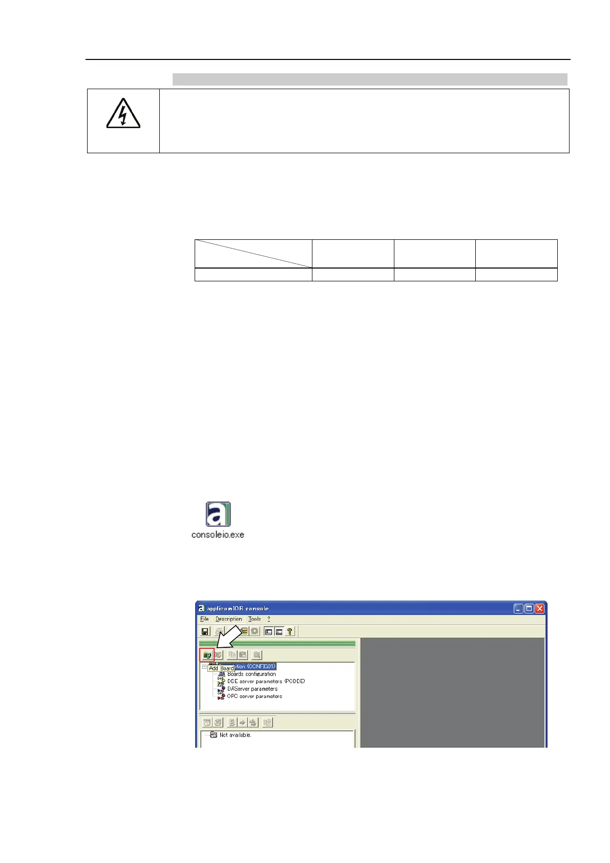
5. Open the [applicomIO Console] installation folder and start the [applicomIO Console]
application.
Following is specified for [applicomIO Console] installation folder as default.
C:\Program Files(x86)\BradCommunications\applicomIO\4.1
6. The [Add New Board] dialog box appears. Add the PROFIBUS-DP master board
manufactured by molex.
Click <Add Board>.