2. Installation
198 RC700 / RC90 Option Fieldbus I/O Rev.14
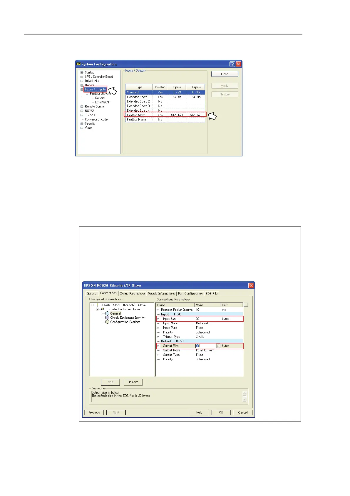
6. Select [Setup]-[System Configuration] and display the [System Configuration] dialog
box.
7. Select [Inputs / Outputs].
8. Confirm that the following items are displayed in “Fieldbus slave”.
Inputs : 512 – ( 512 + Changed number of input (Bits) )
Outputs : 512 – ( 512 + Changed number of output (Bits) )
In this example, Input byte is 20 bytes (160 bits) and 512-671 is displayed in Inputs.
Also, Output byte is 20 bytes (160 bits) and 512-671 is displayed in Outputs.
9. Click <Close>.
When you change the input/output size of EtherNet/IP slave module, you need to
change the input/output size of the slave information registered in the Fieldbus master
device.
Use the window below to change the input/output size of the slave information
registered in the Fieldbus master device by the applicomIO Console application.