2. Installation
202 RC700 / RC90 Option Fieldbus I/O Rev.14
2. Set the CC-Link baud rate. Check the master configuration and set the same baud
rate. Refer to the following table for configuration.
Wiring
The CC-Link connector is a 5-pin open connector. Use the connector attached to the
board for wiring.
Terminal name for each pin
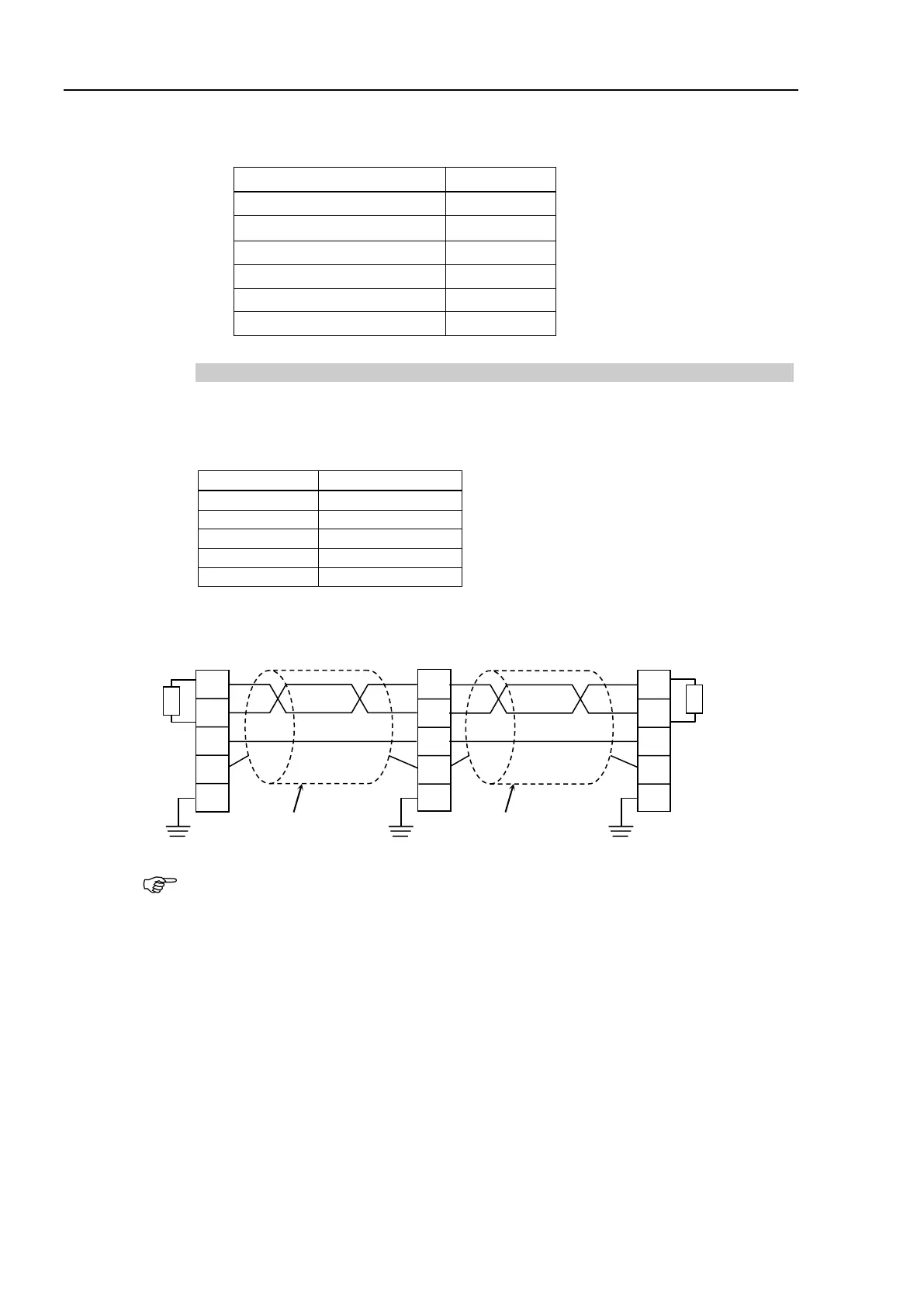
Connect the CC-Link master module and the CC-Link slave board as follows.
DA
DB
DG
SLD
FG
Terminating
Resistor
Master Station
DA
DB
DG
SLD
FG
DA
DB
DG
SLD
FG
CC-Link
Module
Twisted-pair Cable
with Shield
Robot System
CC-Link Board
Terminating
Resistor
Twisted-pair Cable
with Shield
Prepare the cable for CC-Link Ver.1.10 sold in the market as a communication cable.
Install terminating resistors at both ends of the network.
Use the terminating resistors attached to the CC-Link master station.
Make sure to disconnect the connectors only after turning OFF the power supply of the
specific station.
Connect the shield wire for CC-Link to the “SLD” of each unit and ground the both ends
via “FG”.