2. Installation
22 RC700 / RC90 Option Fieldbus I/O Rev.14
If the current capacity consumed in the network exceeds the restriction of cable current
capacity, it is possible to install more than one power supply in the network. If you
attempt to install two or more power supplies, take necessary measures (pulling out a fuse
on the power supply tap, etc.) to avoid conflicts between power outputs from multiple
power supplies.
1A 1A
1A
2A 2A
2A
1A 1A
1A
2A
2A
Trunk Line
Power Supply Tap
Terminating
Resistor
External
Power Supply
24 V DC
Terminating
Resistor
Power Supply Tap
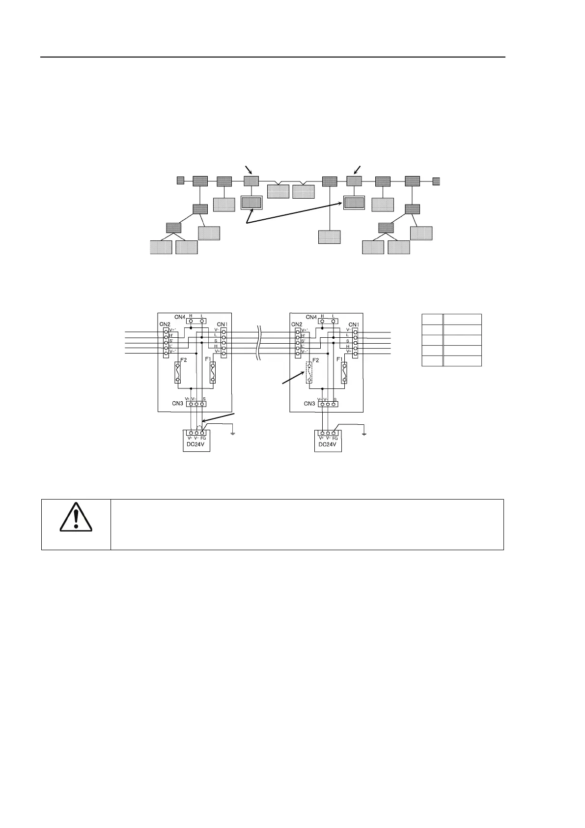
Following figure illustrates a sample wiring. An OMRON power supply tap is used in the
example.
Trunk Line
Pull out
the fuse.
Ground 100 Ω or less.
Ground 100 Ω or less.
If you cannot ground the network with 100 Ω or less,
do not connect V- and FG wires.
Ground the
network at
only one point.
V+ V+
L CAN L
S Shield
H CAN H
V- V-
CAUTION
Carefully connect the wires. Incorrect wiring may cause node malfunction and
severe damage to the entire DeviceNet network.