2. Installation
RC700 / RC90 Option Fieldbus I/O Rev.14 23
Modification and Installation of Communication Cables
Follow the steps described below to modify communication cables and connect them to
connectors.
CAUTION
Be careful not to injure your hands or fingers on any sharp blades or tools used
to modify the cable.
Use appropriate blades and/or tools to modify the cable. Using inappropriate
blades and/or tools may result in bodily injury
and/or equipment damage.
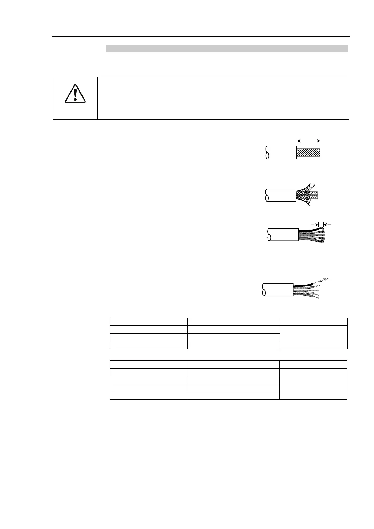
1. Strip approx. 30 mm of the cable covering with extra
care so that you do not scratch on the braided shield
underneath. Do not strip the cable covering more than
necessary. Excess stripping may cause short-circuit
and/or make the cable more sensitive to noise.
2. Carefully expand the meshes of the braided shield.
Under the braided shield, there is one exposed bare
twisted shield wire other than the signal wires and
power wires that are wrapped with aluminum tape.
The shield wire is slightly harder than the mesh.
3. Cut off the expanded braided shield and remove the
aluminum tape around the signal wires and power
wires. Then, strip the insulation from the signal wires
and power wires for a length sufficient to connect
them to crimp terminals.
Twist each stripped signal wire and power wire.
4. Set the crimping terminal on the stripped part of the
wire and crimp it with a crimp tool. The following
crimping terminals are recommended products.
NICHIFU TC series
MH-32
For Thick Cable (power wire)
For Thick Cable (signal wire)
Phoenix Contact AI series
For Thin Cable (power wire)
CRIMPFOX UD6
For Thin Cable (signal wire)
For Thick Cable (signal wire)
For Thick Cable (signal wire)
Peel the coverings in enough
length to connect the wires to