2. Installation
24 RC700 / RC90 Option Fieldbus I/O Rev.14
5. Wrap or cover the cable with vinyl tape or heat-shrink
tubing.
Heat-shrinkable Tube, etc.
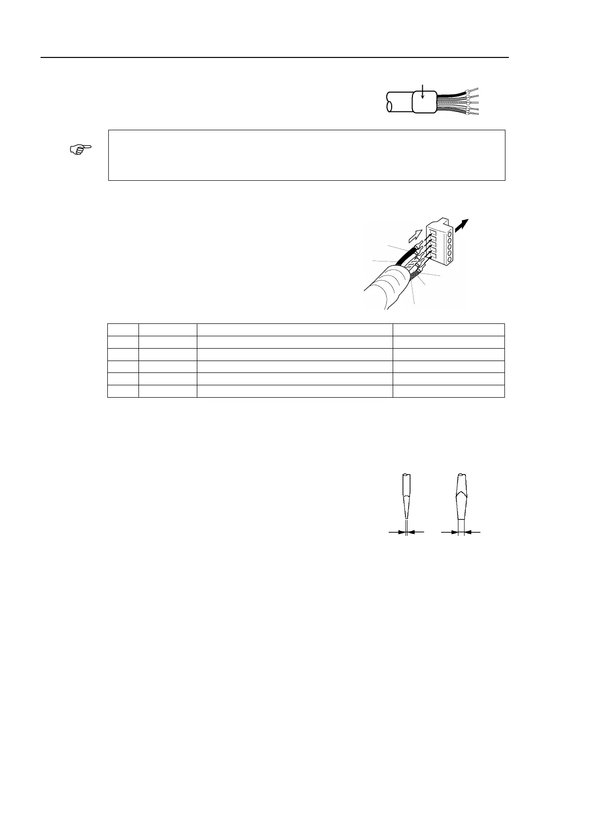
Loosen the screws securing the cables on the connector. If the screws are not
loosened, the wires go into different openings on the rear of connector instead of
the correct openings and the wires cannot be secured.
6. Ensure the correct connector orientation and insert
the signal wires and shield wire to their respective
holes on the connector.
As shown in the figure, insert the wires (black,
blue, shield, white, and red) into the holes in the
order named.
The following table shows the specified colors of
the cables.
Communications Power Supply (negative)
Communications Power Supply (positive)
7. Tighten each screw securing the wires on the connector.
Tighten the screw securing the wire at a correct tightening torque (0.25 to 0.3 N·m).
To prevent thick cable from coming out due to cable tension, install the thick cable with
enough length to allow for stretch.
Use a small flat blade screwdriver that has the correct
width and thickness. If you use a typical screwdriver
whose point is narrow, you cannot deeply insert it into
the hole on the connector.
Specific screwdrivers for DeviceNet connector screw
are:
OMRON : XW4Z-00C
Phoenix Contact : SZF-1 0.6×3.5
Thickness
Width
0.6 mm 3.5 mm