2. Installation
78 RC700 / RC90 Option Fieldbus I/O Rev.14
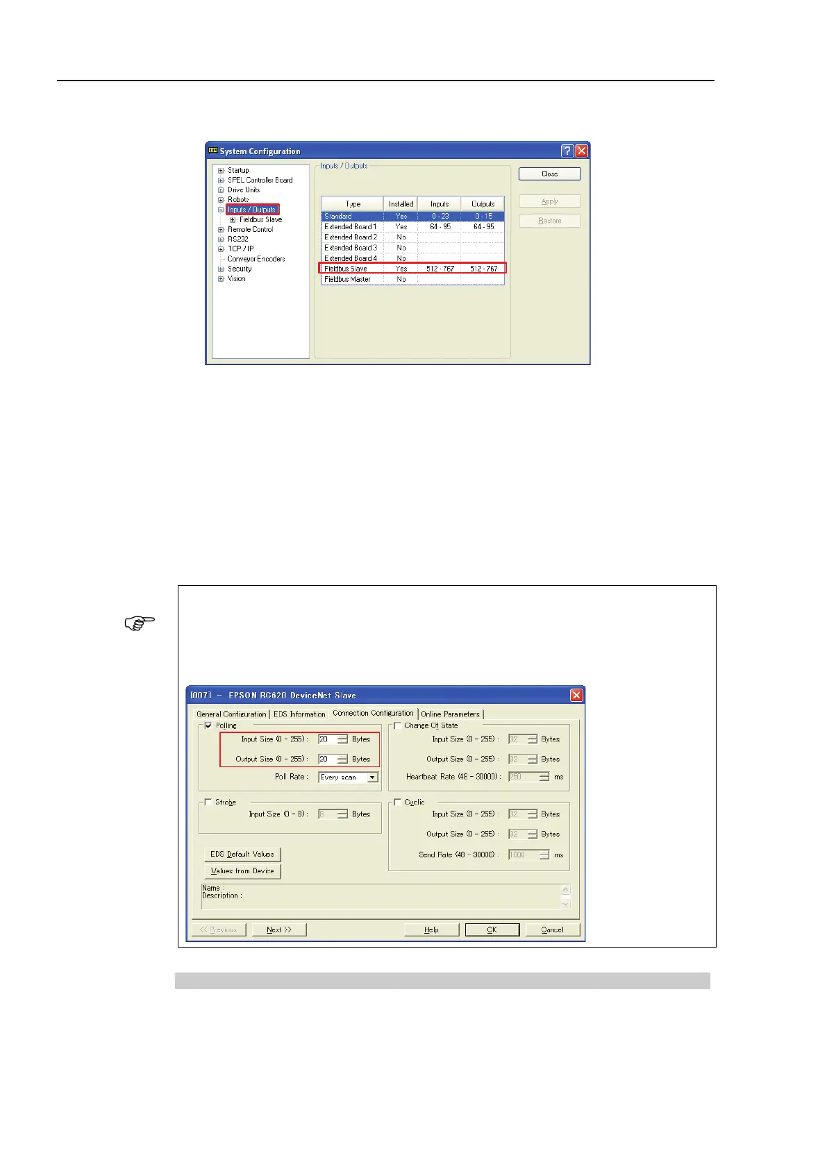
6. Select [Setup]-[System Configuration] and display the [System Configuration] dialog
box.
7. Select [Inputs / Outputs].
8. Confirm that the following items are displayed in “Fieldbus Slave”.
Inputs : 512 – ( 512 + Changed number of input (Bits) )
Outputs : 512 – ( 512 + Changed number of output (Bits) )
In this example, Input byte is 20 bytes (160 bits) and 512-671 is displayed in
Inputs.
Also, Output byte is 20 bytes (160 bits) and 512-671 is displayed in Outputs.
9. Click <Close>.
When you change the input/output size of DeviceNet slave board, you need to change the
input/output size of the slave information registered in the Fieldbus master device.
Use the window below to change the input/output size of the slave information registered
in the Fieldbus master device by the applicomIO Console application.
Electronic Information File (EDS file)
An EDS file is supplied for DeviceNet slave board network configuration. The file is
located in the following folder where the EPSON RC+ 7.0 is installed.
\EpsonRC70\Fieldbus\DeviceNet