2. Installation
80 RC700 / RC90 Option Fieldbus I/O Rev.14
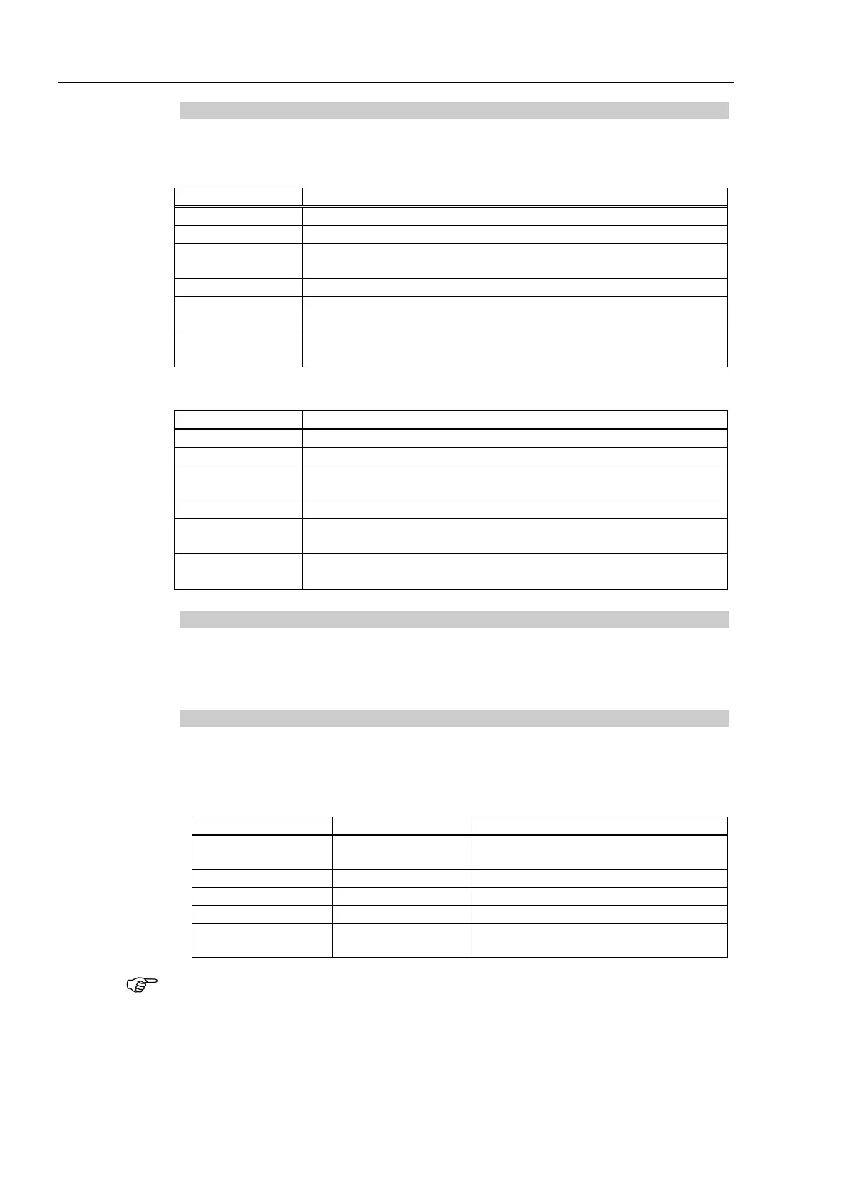
LED Description
LED state represents the status of the fieldbus module.
NS: Network Status LED
Not online / No network power
On-line, one or more connections are established
On-line, no connections established
Critical link failure, fatal event
One or more connections timed-out
MS: Module Status LED
Operating in normal condition
Missing, incorrect or incomplete configuration, device needs
commissioning.
Setting Configure Switch
The DeviceNet slave module requires no configurations.
All the DeviceNet communication configurations are set by the development software
(EPSON RC+ 7.0).
Wiring
DeviceNet connector is a 5-pin open connector. Use the connector attached to the board
for wiring.
Terminal name for each pin
1 V-
Negative bus supply voltage
(DeviceNet bus power)
5 V+
Positive bus supply voltage
(DeviceNet bus power)
Prepare the cable for DeviceNet sold in the market as a communication cable.
Install terminating resistors at both ends of the network.