SC-F9200 Series Revision B
DISASSEMBLY & ASSEMBLY Disassembly and Assembly Procedure 124
SE Group Confidential (Related Staff Only)
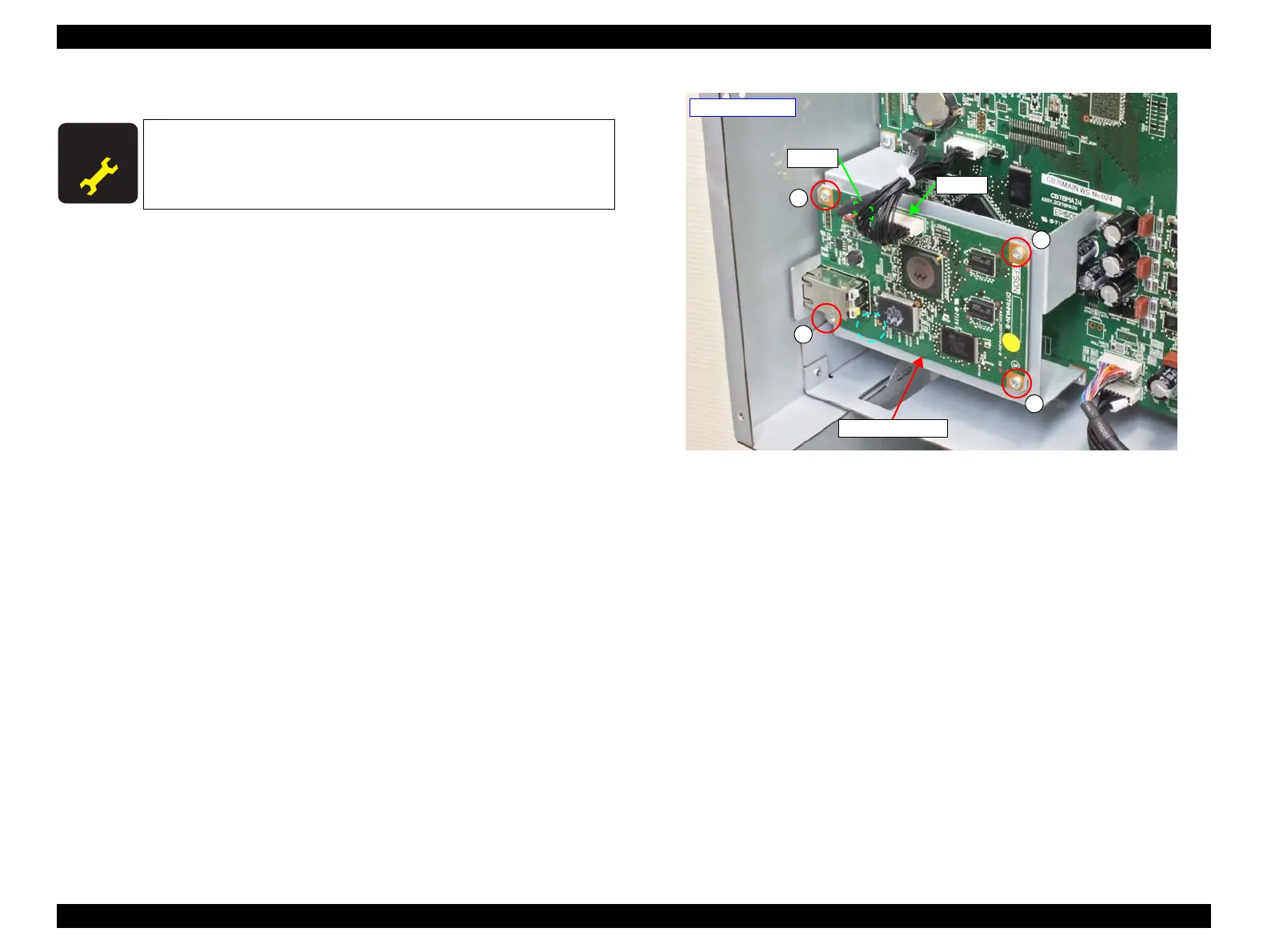
3.4.4.2 Main-B Board
1. Remove the Board Box Cover. (p117)
2. Disconnect the cables from the connectors (CN700, CN701) on the Main-B Board.
3. Remove the four screws, and remove the Main-B Board.
A) Silver M3x6 screw: 4 pcs
Figure 3-48. Removing the Main-B Board
A D J U S T M E N T
R E Q U I R E D
When replacing/removing this part, refer to “4.1.2 Adjustment
Items and the Order by Repaired Part” (p260) and make sure to
perform the specified operations including required adjustment.
A
A
A
A
- Right rear side -
CN701
CN700
Main-B Board

 Loading...


