SC-F9200 Series Revision B
DISASSEMBLY & ASSEMBLY Disassembly and Assembly Procedure 125
SE Group Confidential (Related Staff Only)
3.4.4.3 PSH Board/PSH-B Board
1. Remove the Board Box Cover. (p117)
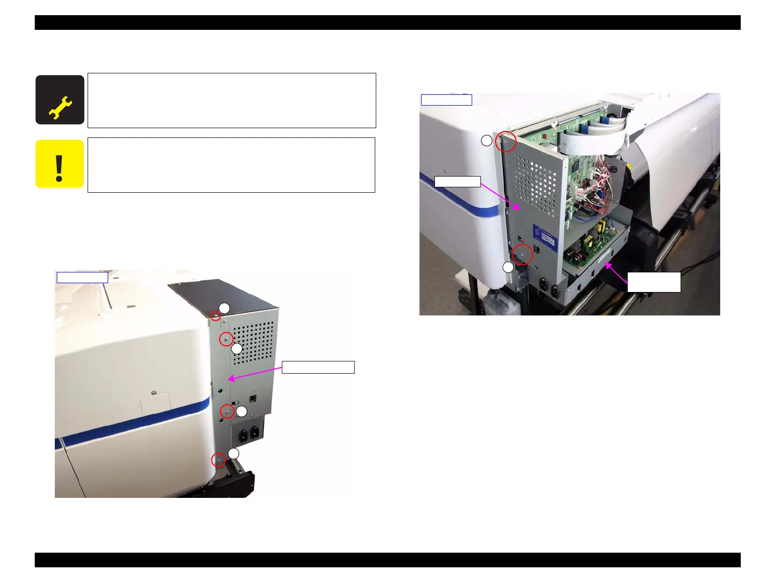
2. Remove the four screws and remove the Board Right Frame.
A) Silver M3x6 screw: 4 pcs
Figure 3-49. Removing the Board Right Frame
3. Remove the two screws, and remove the shield plate.
B) Silver M3x6 screw: 2 pcs
Figure 3-50. Removing the shield plate
A D J U S T M E N T
R E Q U I R E D
When replacing/removing this part, refer to “4.1.2 Adjustment
Items and the Order by Repaired Part” (p260) and make sure to
perform the specified operations including required adjustment.
Always replace the two Power Supply Boards (PSH Board and
PSH-B Board) at the same time.
A
A
A
A
- Right side -
Board Right Frame
B
B
- Right side -
Shield plate
Power Supply
Board Box

 Loading...


