SC-F9200 Series Revision B
DISASSEMBLY & ASSEMBLY Disassembly and Assembly Procedure 126
SE Group Confidential (Related Staff Only)
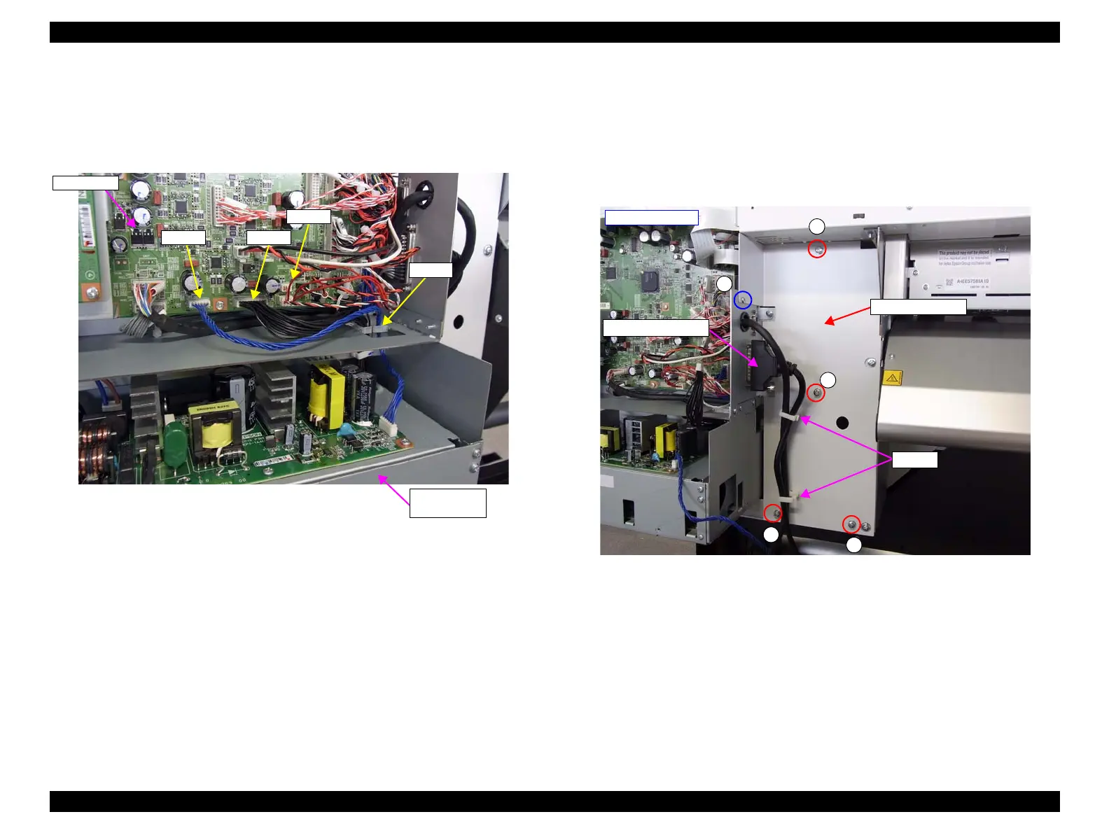
4. Disconnect the cables from the connectors (CN700/CN701/CN40) on the Main
Board.
5. Release the cables disconnected from CN700 and CN701 and CN40 from the
clamp and pull them out of the Power Supply Board Box through the cutout.
Figure 3-51. Releasing the cables
6. Disconnect the connector of the Reel Unit.
7. Release the cable from the two clamps.
8. Remove the five screws, and remove the Right Rear Cover.
C) Silver M4x10 S-tite screw with washer: 4 pcs
D) Silver M3x6 screw: 1 pcs
Figure 3-52. Removing the Right Rear Cover
Main Board
CN701CN700
Clamp
CN40
Power Supply
Board Box
C
C
C
C
D
- Right rear side -
Right Rear Cover
Reel Unit connector
Clamps

 Loading...


