SC-F9200 Series Revision B
DISASSEMBLY & ASSEMBLY Disassembly and Assembly Procedure 127
SE Group Confidential (Related Staff Only)
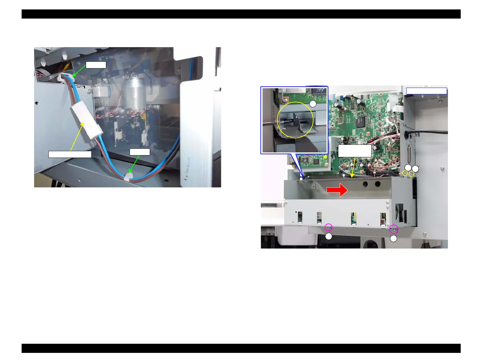
9. Disconnect and release the cables from relay connectors and from the two clamps.
Figure 3-53. Releasing the Cables
10. Remove the five screws that secure the Power Supply Board Box.
E) Silver M4x10 S-tite screw with washer: 2 pcs
F) Silver M3x6 screw: 3 pcs
11. Slide the Power Supply Board Box in the direction of the arrow, and remove it
toward the rear of the printer.
Figure 3-54. Removing the Power Supply Board Box
Relay connectors
Clamp
Clamp
- Right rear side -
Power Supply
Board Box

 Loading...


