SC-F9200 Series Revision B
DISASSEMBLY & ASSEMBLY Disassembly and Assembly Procedure 136
SE Group Confidential (Related Staff Only)
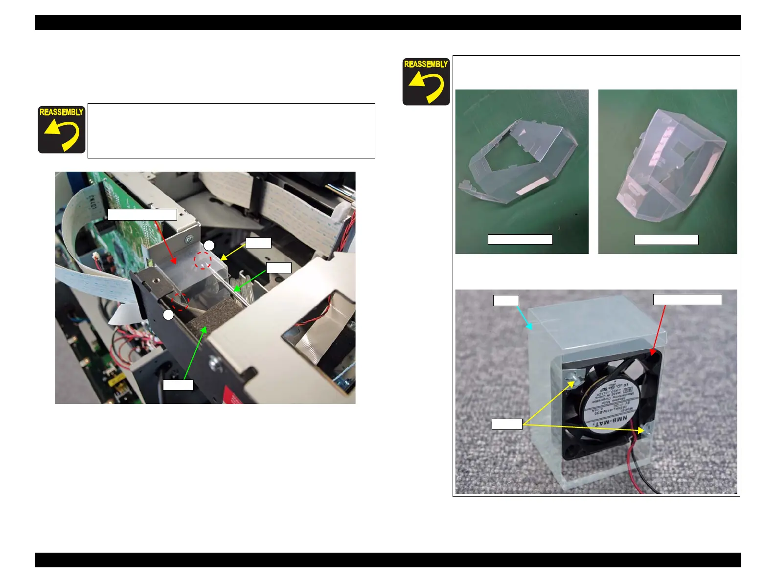
7. Insert a screwdriver into the duct to remove the two screws, and remove the Box
Cooling Fan.
A) Silver M3x12 screw: 2 pcs
Figure 3-68. Removing the Box Cooling Fan
When installing the Box Cooling Fan, be careful not to let the cable
get caught between the fan and the plate. (
Figure 3-67)
A
A
Box Cooling Fan
Duct
Driver
Sponge
The duct provided as an ASP needs to be built as shown before
installing it to the printer.
When installing the Box Cooling Fan, attach it and the screws
to the duct in advance.
Provided like this
Build it like this
Box Cooling Fan
Duct
Screws

 Loading...


