SC-F9200 Series Revision B
DISASSEMBLY & ASSEMBLY Disassembly and Assembly Procedure 135
SE Group Confidential (Related Staff Only)
3.4.4.8 Box Cooling Fan
1. Remove the Media Loading Lever. (p210)
2. Remove the Right Upper Cover. (p103)
3. Remove the Board Box Cover. (p117)
4. Disconnect the cable from the connector (CN408) on the Main Board.
5. Release the cable from the two clamps.
Figure 3-67. Releasing the Cable
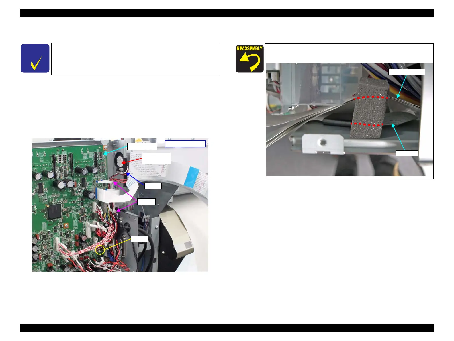
6. Remove the sponge that secures the FFC.
When replacing the Box Cooling Fan, make sure to also replace the
duct.
- Right rear side -
Main Board
Cable
CN408
Box Cooling
Fan
Clamps
When attaching the sponge, route the CR FFC and the Head Relay
FFC separately as shown.

 Loading...


